South Bend, Indiana USA
|
networketi.com
SNOW/ICE CONTROL INSTALLATION MANUAL | PART NO.
23918
REV
B
22
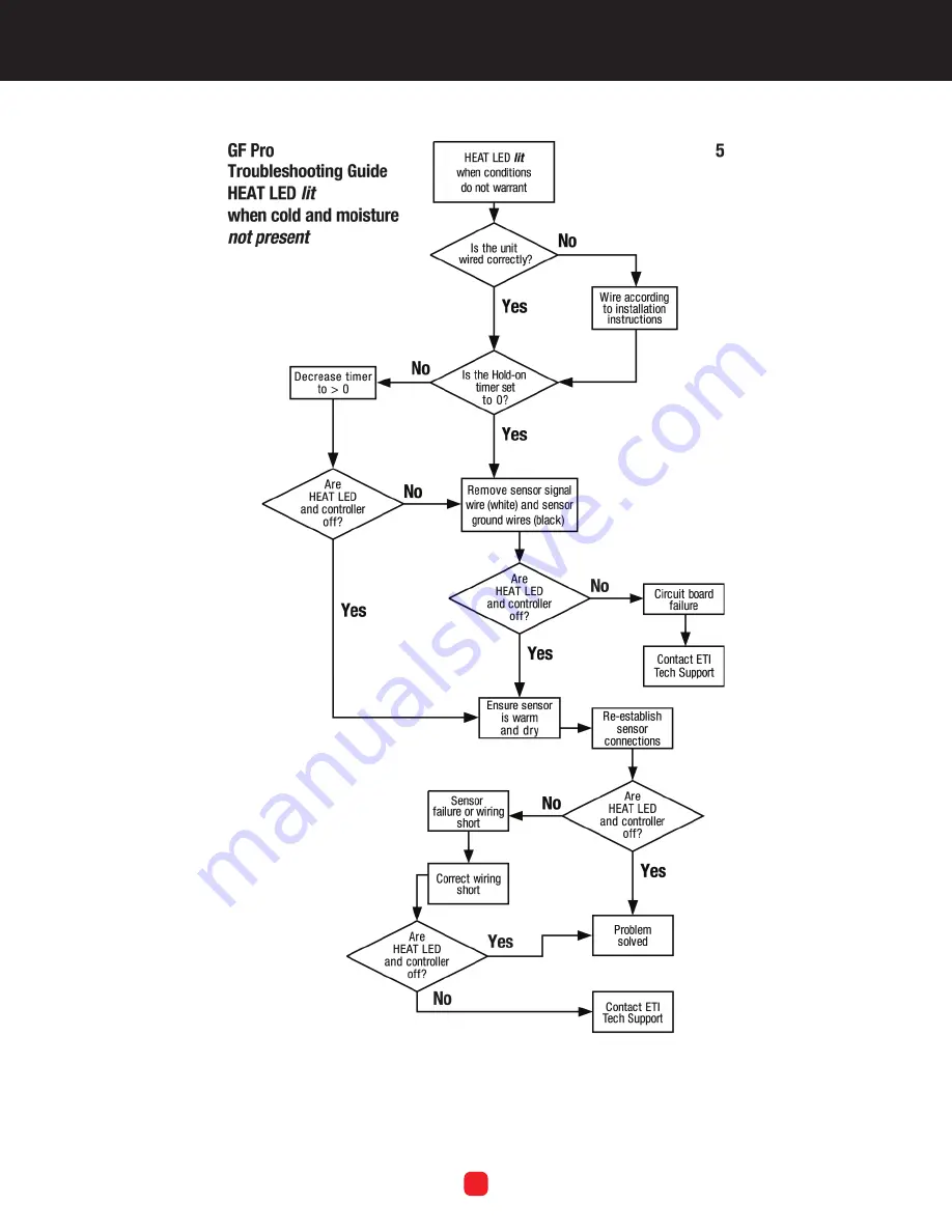
TROUBLESHOOTING FLOWCHART 5
Page 1: ...nfigurations TABLE OF CONTENTS Safety Information and Warnings 3 Product Testing Record 2 Unpacking the Unit 3 Inventory 4 Product Description 5 Selecting the Proper Sensor 5 Available Optional Compon...
Page 2: ...st be grounded to earth to protect against shock and fire hazard Suitable ground fault detection and interrupting systems must be in use at all times to reduce shock and fire hazard and to protect equ...
Page 3: ...e this page to record the results of the testing procedures in this manual Specifically these are a mega ohm test following installation of the heat tape a post installation test of the control box an...
Page 4: ...the outside of the shipping container so that it may be correctly processed upon receipt at Environmental Technology For more information about replacement parts or for a replacement Data Sheet or Man...
Page 5: ...if moisture occurs below this temperature saving energy and ensuring reliable melting Table1 presentstherecommendedsensorcombinations for use with the GF Pro snow and ice control One or two CIT 1 Sen...
Page 6: ...per installation and to facilitate placement wiring routing and function of either or both the optional RCU 4 or temperature sensor it is strongly advised and suggested that these assemblies whether t...
Page 7: ...holes to determine the location of the mounting holes on the wall 2 As desired to hold the box in place during the installation process you may loosely install one or both of the top mounting bolts a...
Page 8: ...ore slack to relieve some of the tension from the wires at the point of the terminal strip then fully tighten the weather tight connection to secure the cable in place If installing an extension onto...
Page 9: ...NSTALLATION MANUAL PART NO 23918 REV B 9 SYSTEM SCHEMATIC DIAGRAMS Figure 2 is a schematic diagram of an entire GF Pro system including the available optional components TABLE 2 Cable Ratings and Conn...
Page 10: ...NSTALLATION MANUAL PART NO 23918 REV B 10 A representative schematic diagram of an SIT 6E pavement sensor installation is shown below in Figure 3 Note how the heat tape and other components do not cro...
Page 11: ...end Indiana USA networketi com SNOW ICE CONTROL INSTALLATION MANUAL PART NO 23918 REV B 11 FIGURE 4 The GF PRO Front Panel PC Board Refer to Figure 4 for useful information regarding the front panel P...
Page 12: ...is the responsibility of the on site installer to assess the overall safety concerns at the site and to disconnect the heat tape as necessary or desired whether before or during this test as well as t...
Page 13: ...voltage between the white and black sensor leads should be less than 2 VDC 4 With the unit cold and the sensing grid moist allow the unit to warm up to above 38 F The SNOW LED should turn off and the...
Page 14: ...ator controls and indicators located on the right side of the panel The controls and indicators are explained in this section Note that because the unit has no ON OFF power switch power runs to the un...
Page 15: ...the Heater Cycle button to stop a current heating cycle unless the SNOW LED is lit SNOW The SNOW LED lights up when any of the sensors detect snow or ice at or below 38 F 3 3 C and stays on until the...
Page 16: ...rent Hold On Time setting unless manually cancelled by pressing the Heater Cycle button a second time It is not necessary for the Hold On Time setting on the control box and the Hold On Time setting o...
Page 17: ...YCLE TIME control dial to the desired setting either higher or lower If a ground fault condition occurs the RCU HEAT LED light will blink on and off To test or reset press the RCU GFEP Test Reset butt...
Page 18: ...EV B 18 TROUBLESHOOTING If any of the following conditions occurs with the unit review the Troubleshooting Charts in this section Prior to removal of anyequipment contactETI TechnicalSupportbetween8 0...
Page 19: ...South Bend Indiana USA networketi com SNOW ICE CONTROL INSTALLATION MANUAL PART NO 23918 REV B 19 TROUBLESHOOTING FLOWCHART 2...
Page 20: ...South Bend Indiana USA networketi com SNOW ICE CONTROL INSTALLATION MANUAL PART NO 23918 REV B 20 TROUBLESHOOTING FLOWCHART 3...
Page 21: ...South Bend Indiana USA networketi com SNOW ICE CONTROL INSTALLATION MANUAL PART NO 23918 REV B 21 TROUBLESHOOTING FLOWCHART 4...
Page 22: ...South Bend Indiana USA networketi com SNOW ICE CONTROL INSTALLATION MANUAL PART NO 23918 REV B 22 TROUBLESHOOTING FLOWCHART 5...
Page 23: ...South Bend Indiana USA networketi com SNOW ICE CONTROL INSTALLATION MANUAL PART NO 23918 REV B 23 TROUBLESHOOTING FLOWCHART 6...
Page 24: ...AL PART NO 23918 REV B 24 HEATER CONNECTION This manual refers to the Snow Switch Model GF Pro control panel manufactured since November 26 2013 which uses an auto select power supply Older units use...
Page 25: ...F 38 F factory preset 40 F configured by magnetic reed switch Front Panel Interface Status indicators SUPPLY green Power on HEAT yellow Heating cycle in progress SNOW yellow Sensor s detect snow GFEP...
Page 26: ...T Email helpdesk networketi com Web networketi com Mail ETI 1850 North Sheridan Street South Bend IN 46628 LIMITED WARRANTY ETI s two year limited warranty covering defects in workmanship and material...