


Section 2
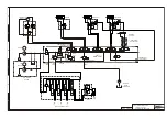
Hydraulic schematic drawing for standard units . . . 2-3
Hydraulic schematic drawing
for units fitted with self level stabilisers . . . . . . . . 2-4
Main control valve . . . . . . . . . . . . . . . . . . . . . . . . . . 2-4
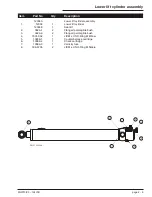
Upper lift cylinder assembly . . . . . . . . . . . . . . . . . . 2-5
Lower lift cylinder assembly . . . . . . . . . . . . . . . . . . 2-6
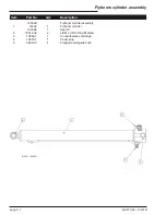
Flyboom cylinder assembly . . . . . . . . . . . . . . . . . . . 2-7
Stabiliser leg cylinder assembly . . . . . . . . . . . . . . . 2-8
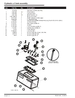
Hydraulic oil tank assembly . . . . . . . . . . . . . . . . . . . 2-9
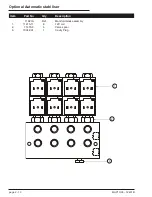
Optional Rotator cylinder assembly . . . . . . . . . . . 2-10
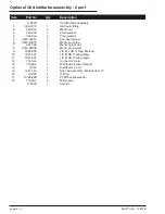
Optional Oil distributor assembly - 2 port . . . . . . . 2-11
Optional Oil distributor assembly drawing. . . . . . . 2-12
Optional Automatic stabiliser. . . . . . . . . . . . . . . . . 2-13
MHP13/35 – 12431B
page 2 - 1
Section 2. - Hydraulics
Summary of Contents for MHP1335
Page 6: ......
Page 24: ...page 1 2 MHP13 35 12431B ...
Page 34: ......
Page 41: ......
Page 56: ......
Page 58: ...page 2 2 MHP13 35 12431B ...
Page 72: ......
Page 74: ...Page 3 4 Electrical schematic Auto stabiliser ...
Page 76: ......
Page 84: ......
Page 96: ......
Page 106: ......