background image


Section 2 - OPERATING INSTRUCTIONS 


WARNING 

DO NOT attempt any maintenance, adjustments or 
service with engine and blade running. STOP engine 
and blade. Remove key. Disconnect spark plug wire 
and secure away from spark plug. Engine and 
components are HOT. Avoid serious burns, allow 
sufficient time for all components to cool. 

 
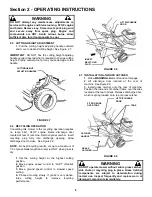
2.5  CUTTING HEIGHT ADJUSTMENT 

1.  Pull the cutting height adjusting handle outward 
and move to desired cutting height. See Figure 2.7. 

 
IMPORTANT:  DO NOT flex the cutting height adjusting 
handle outward beyond what is required to change cutting 
height. Pulling outward too far may cause damage to the 
handle. 


FIGURE 2.7 

 
2.6  RECYCLING OPERATION  
Converting this mower to the recycling operation requires 
no tools. First, STOP engine. Raise discharge door 
located at rear of machine. Remove grass catcher. Insert 
recycling plug fully into discharge opening. Allow 
discharge door to close.  See Figure 2.8. 
 
NOTE: For best recycling results, cut up to a maximum of 
1/3 of grass blade length and recycle ONLY when grass is 
dry. 
 

1.  Set the cutting height at the highest cutting 
position. 
2.  Move engine speed control to “FAST” (Rabbit) 
position. 
3. Move ground speed control to slowest speed 
setting. 
4. Proceed mowing slowly. If grass is very dense, 
raise cutting height to improve recycling 
performance. 


FIGURE 2.8 

 
2.7  INSTALLATION of GRASS CATCHER 

1.  Follow WARNING statement found on this page. 
2. Lift discharge door located at the rear of 
machine. See Figure 2.9. 
3. Install grass catcher onto the rear of machine. 
Position the rod ends of catcher frame over the tabs 
located at the rear of deck. Release discharge door, 
which is spring loaded, onto top of grass catcher.   


FIGURE 2.9 


WARNING 

DO NOT operate mower without entire grass catcher, 
side chute or recycling plug in place. Grass Catcher 
components are subject to deterioration during 
normal use. Inspect frequently and replace worn or 
damaged components immediately. 


CUTTING HEIGHT 
ADJUSTING HANDLE 

GRASS 
CATCHER 

LIFT DISCHARGE 
DOOR 

FIT ROD ENDS 
OVER TABS 

TABS 

CATCHER 
HANDLE 

LIFT DISCHARGE 
DOOR 

INSERT 
RECYCLING 
PLUG 

Summary of Contents for ELP21702BV

Page 1: ...Briggs Stratton 21 21 Cutting Width V Over Head Valve Engine Thank you for buying a SNAPPER Product Before operating your Walk Behind read this manual carefully and pay particular attention to the IMPORTANT SAFETY INSTRUCTIONS on Pages 2 3 Remember that all power equipment can be dangerous if used improperly Also keep in mind that SAFETY requires careful use in accordance with the operating instru...

Page 2: ...tra care with grass catchers or other attachments these affect the handling and the stability of the machine PREPARATION 1 Read understand and follow instructions and warnings in this manual and on the mower engine and attachments Know the controls and the proper use of the mower before starting 2 Only mature responsible persons shall operate the machine and only after proper instruction PREPARATI...

Page 3: ...ng repairing or inspecting make certain engine blade and all moving parts have STOPPED Disconnect and secure spark plug wire away from plug to prevent accidental starting OPERATION Continued From Previous Column 11 STOP engine and wait until the blade comes to complete STOP before removing grass bag and or clearing grass 12 DO NOT operate mower without the entire grass catcher or guards in place D...

Page 4: ...mission Grease 9 Check Wheel Drive Control 9 Check Mower Blade 10 Check Engine to Transmission Drive Belt 10 Service Annually 10 Engine 10 Air Filter 10 Engine Oil 10 Storage Procedure 10 SECTION 4 ADJUSTMENTS AND REPAIR 11 15 Mower Blade Replacement 11 Blade Sharpening 11 12 Wheel Drive Control Adjustment 12 Belt Service 13 Battery Service 14 15 TROUBLESHOOTING 16 MAINTENANCE SCHEDULE 17 Maintena...

Page 5: ...MENCLATURE The nomenclature information above Figure 1 1 shows the essential parts of the SNAPPER WALK BEHIND MOWERS It is recommended that all operators of the mower become thoroughly familiar with the controls parts and operation of the mower before operating Specific details involving the engine are found in the separate engine owner s manual Study these manuals before operating and keep both h...

Page 6: ...battery preparation 2 1 6 Add fuel to tank after pushing the mower outside where fumes can safely dissipate Make sure cap is tightened after refueling Refer to Engine Owners Manual for specifications 2 1 7 Clean exterior surfaces of cutting deck and engine of any accumulation of spilled fuel dirt grass oil etc Keep engine air intake screen and cooling fins clear at all times 2 2 STARTING OPERATION...

Page 7: ...e by releasing blade control 3 Pull blade control against handle 4 Pull rope start handle to crank engine 5 After engine starts move engine speed control to the FAST Rabbit position and allow a brief warm up until engine runs smooth 2 2 3 PROPELLING MOWER 1 Move ground speed control to the desired speed position See Figure 2 5 2 Move wheel drive control against handle to engage wheel drive and pro...

Page 8: ...ycling results cut up to a maximum of 1 3 of grass blade length and recycle ONLY when grass is dry 1 Set the cutting height at the highest cutting position 2 Move engine speed control to FAST Rabbit position 3 Move ground speed control to slowest speed setting 4 Proceed mowing slowly If grass is very dense raise cutting height to improve recycling performance FIGURE 2 8 2 7 INSTALLATION of GRASS C...

Page 9: ...il drain plug 4 Loosen with ratchet and short extension but do not remove oil drain plug Loosen plug until you can turn it with your fingers 5 Lower the mower down and place the piece of wood under left rear wheel Reach back under mower and remove drain plug and allow oil to drain out completely in pan Some oil may spill onto drive belt and hands immediately wipe hands clean with cloth rags Dispos...

Page 10: ...efore operating mower Refer to Section BELT SERVICE for replacement instructions FIGURE 3 2 3 3 SERVICE ANNUALLY Perform all maintenance as described in the maintenance schedule 3 3 1 Engine Service engine according to engine owner s manual 3 3 2 Air Filter Refer to engine owner s manual for service instructions 3 3 3 Engine Oil Refer to engine owner s manual for service instructions 3 4 STORAGE P...

Page 11: ...D BLADE WEAR LIMIT 1 Follow WARNING statement found on this page 2 Inspect blade frequently for signs of excessive wear or damage See Figure 4 1 FIGURE 4 1 WARNING DO NOT use a cutting blade that shows signs of excessive wear or damage Refer to Section MOWER BLADE REPLACEMENT for proper blade inspection and service procedures 4 1 2 BLADE SHARPENING 1 Follow WARNING statement found on this page 2 T...

Page 12: ...or cracking fraying severed or belt strands exposed Replace belt before operating mower 2 To check for proper drive belt tension STOP engine Shift ground speed control to 1 st and engage the wheel drive control 3 With the wheel drive control engaged pull the mower handles moving the mower rearward Observe the rear wheels 4 If the rear wheels slide on the surface no rotation the belt is properly te...

Page 13: ...low WARNING statement found on this page 2 Remove the retaining screws that secure the belt cover Remove the belt cover See Figure 4 5 3 Disconnect belt from transmission pulley 4 Tilt mower up on its rear wheels Do not tilt mower with spark plug or carburetor down 5 Remove the retaining bolts and nuts that secure the blade Remove blade See Figure 4 5 6 Remove the belt from around engine pulley 7 ...

Page 14: ...2 Plug battery harness into main harness See Figure 4 9 4 4 3 BATTERY SERVICE The battery supplied with the electric start model mowers is a sealed lead acid type battery After initial activation the battery is sealed No fluid level maintenance is required DO NOT attempt to check or adjust fluid level in battery 1 Remove battery Refer to Section BATTERY REMOVAL 2 Place battery in a well ventilated...

Page 15: ...attery terminals Use the BATTERY CONDITION CHART below to determine the state of charge Slow charge the battery as required to bring to full charge 4 4 6 NEW BATTERY PREPARATION Snapper through your local authorized Snapper dealer provides replacement battery kits The kit includes a battery hardware harness electrolyte and instructions The electrolyte acid is a very dangerous corrosive and poisono...

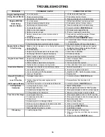
Page 16: ...ne Loses Power 1 Engine air pre cleaner or air cleaner dirty 1 Clean or replace filters 2 Spark plug faulty 2 Service spark plug 3 Water debris or stale fuel in fuel system 3 Drain and clean fuel system 4 Debris build up on engine cooling screen 4 Clean all debris from engine cooling screen Excessive Vibration 1 Damaged out of balance or bent mower blade 1 Service mower blade 2 Loose blade compone...

Page 17: ... Clean Debris Accumulation Page 10 X Transmission Grease Check Grease Level Pages 9 X X Battery Service Battery Pages 14 15 X X Change oil every 25 hours when operating under heavy load or high temperatures Clean more often under dusty conditions or when air debris is present MAINTENANCE REPLACEMENT PARTS MAINTENANCE PARTS Engine Speed Control Briggs Engine 2 9036 Engine Speed Control Kawasaki Eng...

Page 18: ...ade 5 SPARK PLUG Warns of potential electrical shock from plug while engine is running 6 ENGINE SPEED CONTROL Indicates direction to increase Engine RPM Rabbit decrease Engine RPM Turtle WARNING DECAL 22841 SPARK PLUG SYMBOL P N 29779 WARNING DECK DECAL P N 7 2921 SAFETY ALERT SYMBOL OBSERVE AND FOLLOW ALL SAFETY INSTRUCTIONS READ UNDERSTAND AND FOLLOW INSTRUCTIONS AND WARNINGS IN OPERATOR S MANUA...

Page 19: ...f cut 9 NOISE CONTROL This unit is certified to be within the 100 dBA sound power limit at the specified Engine RPM 10 EUROPEAN PERFORMANCE Maximum level of vibration measured at the operators hand is 23 4 m sec2 11 OPERATOR PRESENCE CONTROL Pull control against handle to start engine and blade Release control to stop engine and blade 12 GROUND DRIVE Pull lever against handle to engage drive Relea...

Page 20: ...cates location of engine air filter To service the filter read and follow the engine operating and maintenance instructions 15 WARNING Located on the right side of the Mower Deck It advises operator of the danger of the rotating blade CHUTE DEFLECTOR DECAL P N 4 6924 AIR FILTER SYMBOL P N 2 9781 WARNING DECAL P N 1 3010 ...

Page 21: ...iginal purchase date SNAPPER will not be responsible for any installation cost incurred The battery warranty only covers original equipment batteries and does not cover damage to the battery or machine caused by neglect or abuse destruction by fire explosion freezing overcharging improper maintenance or use of improper electrolyte There is no other express warranty DISCLAIMER OF WARRANTY Implied w...

Page 22: ..._____________________________________ ___________________________________________________________________ ___________________________________________________________________ ___________________________________________________________________ ___________________________________________________________________ ___________________________________________________________________ ______________________...

Page 23: ..._____________________________________ ___________________________________________________________________ ___________________________________________________________________ ___________________________________________________________________ ___________________________________________________________________ ___________________________________________________________________ ______________________...

Page 24: ...f you have any questions about your Snapper product contact your local authorized Snapper dealer or contact Snapper Customer Service at Snapper McDonough GA 30253 Phone 1 800 935 2967 COPYRIGHT 2003 SNAPPER PRODUCTS INC ALL RIGHTS RESERVED MANUAL No 7 5519 I R 3 11 03 WARNING ENGINE EXHAUST SOME OF ITS CONSTITUENTS AND CERTAIN VEHICLE COMPONENTS CONTAIN OR EMIT CHEMICALS KNOWN TO THE STATE OF CALI...

Reviews: