background image

SECTION 1 – FAMILIARIZATION 


1.1  INTRODUCTION 

This manual has been prepared for the operators of 
Turf Cruiser™ & Trail Cruiser™ utility vehicles. Its 
purpose, aside from recommending standard operating 
procedures and routine service requirements, is to 
promote SAFETY through the use of accepted 
operating practices. 

Read, Understand and Follow 

the 

IMPORTANT SAFETY INSTRUCTIONS on Pages 2 
thru 6 of this manual and 

All 

SAFETY messages on the 

utility vehicle and its accessories before operating. 


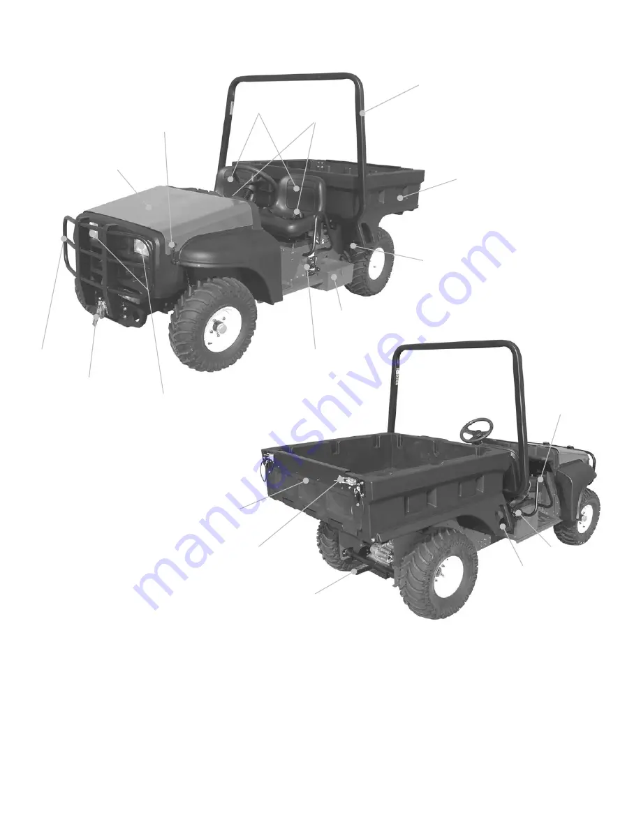
1.2  NOMENCLATURE 

The nomenclature information above shows the 
essential parts of the vehicle. It is recommended that all 
operators of this equipment become thoroughly familiar 
with the controls, components, and operation of this 
machine before operating.  Specific details involving the 
engine are found in the separate engine owner’s 
manual.  Study these manuals before operating and 
keep both handy for future reference. 


ELECTRIC 
WINCH * 

BRUSH 
GUARD * 

CARGO BED 

HOOD  
RETAINING 
LATCH (2) 

OPERATOR PROTECTIVE 
STRUCTURE (OPS) 

SEAT  
BELT (2) 

STORAGE 
COMPARTMENT 

8

CARGO BED 
LATCH LEVER 

POWERLINK™ 
GENERATOR SYSTEM *

TOOL 
BOX 

TAILGATE 

RECEIVER 
HITCH 

FUEL FILL 

TAILGATE 
LATCH (2) 

CARGO BED  
LIFT HANDLE  
(ONE EACH SIDE) 

SEAT SIDE 
BAR (ONE 
EACH SIDE) 

HEADLIGHTS 

* NOT ON ALL MODELS 

SEAT (2) 

Summary of Contents for 7085632

Page 1: ...mind that SAFETY requires careful use in accordance with the operating instructions and common sense NOTE Specifications are correct at time of printing and are subject to change without notice Actual sustained equipment horsepower will likely be lower due to operating limitations and environmental factors Turf Cruiser Trail Cruiser utility vehicles are manufactured by Snapper Products Inc McDonou...

Page 2: ...to operate the machine All operators must be properly trained in the safe operation of the machine be 16 years old or older and possess a valid driver s license 4 ALLOW only adults or responsible teenagers 16 years old or older with mature judgment under close adult supervision to operate machine 5 BEFORE BACKING stop machine completely LOOK and SEE behind and down for children pets and hazards be...

Page 3: ... Tire inflation pressure must be maintained as specified on the machine and in this manual CARRYING LOADS Continued 9 Always release accelerator and apply brake when descending slopes to maintain safe speed 10 DO NOT replace tires with different size or construction Tire size and construction are critical to the proper handling and stability of the machine Use only tires approved by manufacturer T...

Page 4: ...ntainers inside a vehicle or on a truck or trailer bed with a plastic liner Always place the containers on the ground away from the vehicle before filling SAFE HANDLING OF GASOLINE Continued 7 Remove gas powered equipment from the vehicle or trailer and refuel it on the ground If this is not possible then refuel equipment using a portable container rather than a gasoline dispenser nozzle 8 DO NOT ...

Page 5: ...nching operation 1 Read understand and follow all warnings and instructions in the winch operator s manual before performing a winching operation ELECTRIC WINCH OPERATION Continued 2 The wire rope must be free of tension and the wire rope drum fully stopped before engaging or disengaging the clutch 3 DO NOT use a recovery strap or other types of stretchable straps in a winching operation 4 Use the...

Page 6: ...plug opening The spark could ignite the gas exiting the engine 13 DO NOT change engine governor speed settings or over speed engine 14 DO NOT modify machine Use only genuine replacement parts to assure that original standards and performance are maintained 15 Have machine serviced by an authorized SNAPPER dealer at least once a year and have dealer install any new safety devices 16 POWERLINKTM On ...

Page 7: ...ring King Pins 23 Check Wheel Lug Nuts 23 Check Brakes 23 Check Interlocks 24 Service Every 25 Operating Hours 24 Check Battery 24 Check Drive Belt 24 Engine Service 24 Service Every 50 Operating Hours 24 25 Check Wear Pads on Driven Clutch 24 Check Drive Clutch 25 Change Engine Oil 25 Service Every 100 Operating Hours 25 Change Engine Oil Filter 25 Service Every 200 Operating Hours or Yearly 25 C...

Page 8: ...e information above shows the essential parts of the vehicle It is recommended that all operators of this equipment become thoroughly familiar with the controls components and operation of this machine before operating Specific details involving the engine are found in the separate engine owner s manual Study these manuals before operating and keep both handy for future reference ELECTRIC WINCH BR...

Page 9: ...IMPORTANT NOTE DUE TO SPACE LIMITATIONS THE BRAKE AND ACCELERATOR PEDALS ARE OFFSET TO THE RIGHT OF THE OPERATOR S SEAT OPERATOR MUST EXERCISE EXTREME CAUTION WHEN FIRST OPERATING THE VEHICLE UNTIL FAMILIAR WITH PEDAL OFFSET CHOKE KNOB TRANSMISSION SHIFT LEVER 12V ACCESSORY PLUG BED LIFT SWITCH OPTIONAL PARKING BRAKE KNOB IGNITION SWITCH BEVERAGE HOLDERS CONTROL CONSOLE HEADLIGHT SWITCH HAND GRIP ...

Page 10: ...AFETY SIGNS HEADLIGHT SWITCH IGNITION SWITCH SPEEDOMETER FUEL GAUGE COMBO CONSOLE CONTROLS DANGER OPERATOR PROTECTIVE STRUCTURE ON HEADLIGHTS OFF TRANSMISSION SHIFTER CHOKE PARK BRAKE DIFFERENTIAL LOCK CARGO BED LIFT OPTIONAL 10 ...

Page 11: ...G WARNING TO PREVENT FIRE WARNING HOT SURFACE SPECIFICATIONS MAINTENANCE DO NOT OPERATE MACHINE WITH CARGO BED RAISED DO NOT RAISE CARGO BED WHEN LOADED OR ON SLOPES ALL LOADS MUST BE CENTERED NO HIGHER THAN SIDES OF CARGO BED AND SECURED TO PREVENT SHIFTING WARNING CARGO BED LOADS POWERLINK WARNINGS 11 ...

Page 12: ...OW LOADS ON SLOPES IN EXCESS OF 10 18 GRADE DO NOT TOW A LOAD YOU CANNOT SAFELY CONTROL DO NOT OVERLOAD OR EXCEED RATED CAPACITY OF MACHINE MAXIMUM ONE OPERATOR AND ONE PASSENGER 400 LBS TOTAL BOTH MUST BE SEATED IN SEATS PROVIDED WITH SEAT BELT LATCHED AND ADJUSTED TO A SNUG FIT DO NOT CARRY CHILDREN OR OTHERS IN CARGO BED ON HOOD ATTACHMENTS OR TOWED EQUIPMENT KEEP CHILDREN OUT OF WORK AREA AND ...

Page 13: ...tick See Figure 2 1 Use MOBILFLUID 424 or equivalent IMPORTANT Do Not overfill Always fully thread dip stick when checking transmission fluid levels FIGURE 2 1 2 1 6 Add Fuel to tank Refer to Engine Owner s manual for fuel specifications Make sure fuel filler cap is tight after fueling IMPORTANT NOTE Always fuel machine out of doors where fumes can safely dissipate Do not smoke while fueling 2 1 7...

Page 14: ...r slippery surfaces or where traction is doubtful 2 2 2 Park Brake To engage or set the park brake 1 Pull park brake knob up and hold See Figure 2 3 2 Depress Brake Pedal firmly There will be a clicking sound as the pedal is depressed indicating that the brake has engaged the lock mechanism Two clicks should be sufficient to hold the machine To disengage or release the park brake 1 Depress brake p...

Page 15: ...luggish Engine must immediately return to idle speed when pedal is released 2 2 6 Choke The choke control is used to help start a cold engine Pull choke knob up to apply turn on choke Push knob down to open turn off choke Do not operate the engine with the choke on NOTE After starting a cold engine the choke may be partially applied to assist running during the warm up period Refer to page 9 Contr...

Page 16: ...ll be displayed for two 2 hours and will continue even if oil is changed within the two hour period After two hours whether oil is changed or not display will revert back to hourmeter tachometer function 2 2 13 Cargo Bed The manual lift cargo bed is secured in the lowered position by two spring latches located on either side of the machine Pull outward on the latch lever located behind the left ca...

Page 17: ...MUST BE FULLY STOPPED AND THE ENGINE AT IDLE SPEED BEFORE SHIFTING GEARS ALWAYS MOVE THE SHIFT LEVER WITH A QUICK AND POSITIVE MOTION TO AVOID GRINDING GEAR 2 4 1 Starting Motion Forward A Complete pre start checklist B Operator must be seated with seat belt securely latched and adjusted to a snug fit C Park brake must be set and the transmission in Neutral D POWERLINK generator speed control leve...

Page 18: ...achine with differential locked Unlock differential when increased traction is not required A Bring machine and wheels to a complete stop IMPORTANT All motion must be stopped before attempting to lock the differential B Move the differential lock lever to the front of the slot and latch in the Locked position C Shift transmission to desired direction D Move accelerator pedal slowly The differentia...

Page 19: ... brakes with a firm steady force Avoid sudden stops and skidding tires P The use of a helmet face shield or safety glasses and substantial clothing is recommended Q Be familiar with the area that the machine is operated in Stay alert for holes and hidden hazards 2 8 CARRYING LOADS Carrying loads affects the handling stability and braking of the machine Improper loads shifting loads excessive speed...

Page 20: ...windshield sunshade cab or cause the hood to suddenly blow open The machine should be backed on the vehicle or trailer Reduce speed when transporting machine 2 11 WATER CROSSING Operating machine in water crossing streams rivers and creeks is not recommended Fast moving water can quickly move the machine off course causing loss of control that may result in injury or death Even shallow still water...

Page 21: ...prior to the loss of power B Verify the reset button on the GFCI has not been tripped The reset button will pop out if tripped To restore press the reset button C The engine must be running the park brake set and the transmission in neutral D Actuate the POWERLINKTM reset switch Move the switch to the OFF position and then return it to the ON position NOTE The system must be reset any time the eng...

Page 22: ...e Figure 3 1 FIGURE 3 1 3 Place a 2 quart minimum capacity container under the drain plug 4 Loosen or remove oil fill cap on engine 5 Turn drain plug counter clockwise and remove Allow sufficient time for oil to drain completely 6 Reinstall the oil drain plug Torque plug to 12 ft lb 7 Fill engine crankcase to proper level with new oil Refer to the Engine Owner s Manual for crankcase capacity and o...

Page 23: ...ase gun 6 Repeat on right axle coupling 7 Locate grease fitting on left right king pins See Figure 3 4a 8 Apply 4 shots of General Purpose grease from a grease gun FIGURE 3 4a 3 2 6 Check Wheel Lug Nuts 1 Torque all lug nuts to 75 ft lb 3 2 7 Check Brakes 1 Move machine to an open area free of obstacles children and others 2 Set park brake firmly 2 or more clicks 3 Start engine and shift transmiss...

Page 24: ...can continue to run if you sit back down in the seat before it dies completely POWERLINK equipped models only 18 Start engine 19 Shift Transmission to Forward 20 Reach down and raise generator speed control lever Engine should begin to die Drop lever 21 Shift Transmission to Reverse 22 Reach down and raise generator speed control lever Engine should begin to die Drop lever 23 Shift Transmission to...

Page 25: ...ft bottom side of transmission case Drain fluid into 6 quart minimum capacity pan See Figure 3 6 FIGURE 3 6 2 Allow fluid to drain completely Reinstall drain plug and tighten securely 3 Fill transmission with 5 6 qt of MOBILFLUID 424 or equivalent 4 Check fluid level and top off as needed Do Not over fill 3 6 3 Replace Fuel Filter 1 Engine must be cool before proceeding 2 Remove clamps from filter...

Page 26: ...on Maintenance Check Brakes If adjustment is required complete each of the following steps carefully Always verify that the brakes function properly after performing any brake adjustments Do Not operate the machine if the brakes are not functioning properly WARNING DO NOT operate machine if brakes are not functioning properly Adjust repair or replace as necessary Contact your local authorized deal...

Page 27: ... and secure away from plug Engine and components are HOT Avoid serious burns allow all parts to cool before working on machine 4 3 BATTERY NOTE The battery in this machine is maintenance free It has been filled to the proper level with acid and is sealed Do not attempt to open the battery 4 3 1 Battery Removal 1 The battery is located under operator s seat Remove seat knobs and carefully tilt forw...

Page 28: ...ith new battery WARNING Keep all sparks flame and fire away from area when charging battery WARNING DO NOT attempt to charge battery while installed in the machine DO NOT use BOOST chargers on the battery 4 3 4 Battery Storage If machine is to be stored out of season it is recommended the battery be removed charged and stored 1 Remove battery Refer to Section BATTERY REMOVAL 3 Bring battery to ful...

Page 29: ... to shift into Reverse turn link clockwise 2 3 turns 4 Retighten jam nut against link start vehicle and check shifter operation 5 Repeat steps 1 4 as needed FIGURE 4 6 WARNING DO NOT attempt any adjustments maintenance service or repairs with the engine running STOP engine Set park brake Shift transmission to Neutral Remove key Remove spark plug wire from spark plug and secure away from plug Engin...

Page 30: ...27 SECTION 5 ELECTRICAL 30 ...

Page 31: ...28 SECTION 5 ELECTRICAL 15 AMP FUSE 30 AMP FUSE 30 AMP FUSE 31 ...

Page 32: ...nk empty 3 Fill fuel tank with fresh fuel to proper level 4 Engine air cleaner dirty 4 Clean or replace filter 5 Spark plug defective or gap set improperly 5 Service spark plug s 6 Fuel filter restricted 6 Replace fuel filter 7 Water debris or stale fuel in fuel system 7 Drain and clean fuel system Engine Loses 1 Excessive load on engine 1 Reduce load Power 2 Engine air cleaner dirty 2 Clean or re...

Page 33: ...ry Check Charge Battery Page 27 28 X Tires Check Pressures Page 13 X Drive Belt Check For Wear And Replacement Pages 24 26 X X Lubrication Points Grease or Oil Page 23 X X X Transmission Check Fluid Level Page 23 X Tires Inspect Page 23 X Transmission Change Fluid Page 25 X X Tires Torque Lug Nuts Page 23 X Interlocks Verify Function Page 24 X Drive Clutch Inspect Wear Pads Page 24 X Drive Clutch ...

Page 34: ...riod with free replacement if required for one 1 year from the original purchase date SNAPPER A Division of SIMPLICITY Manufacturing Inc will not be responsible for any installation cost incurred The battery warranty only covers original equipment batteries and does not cover damage to the battery or machine caused by neglect or abuse destruction by fire explosion freezing overcharging or improper...

Page 35: ..._____________________ Retailer s Phone Number ___________________________________________________ It is very important that you register your purchase to ensure warranty coverage Please mail your product registration card to Snapper Products Inc P O Box 1379 McDonough Georgia 30253 Or you may register on line at www snapper com You can contact us at our web site or if you would like to speak with ...

Page 36: ...your Snapper product contact your local authorized Snapper dealer or contact Snapper Customer Service at Snapper McDonough GA 30253 Phone 1 800 935 2967 MANUAL CONTENT COPYRIGHT 2004 SNAPPER A DIVISION OF SIMPLICITY MFG INC ALL RIGHTS RESERVED MANUAL No 7026153 Rev 2 11 11 04 TP 100 5107 2 GC N WARNING ENGINE EXHAUST SOME OF ITS CONSTITUENTS AND CERTAIN VEHICLE COMPONENTS CONTAIN OR EMIT CHEMICALS...

Reviews: