


3
STEP 8: Driven disc to drive disc adjustment is set up at
the factory. In case driven disc may need adjustment,
proceed as follows:
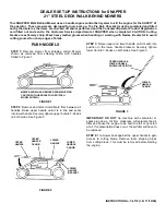
A. Place speed control rod in the number six speed
position. See Figure 7.
FIGURE 7
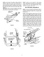
B. Remove driven disc spring from driven disc
assembly as shown. Loosen connector hex-nut. See
Figure 8.
FIGURE 8
C. Slide driven disc assembly over until 1/8” from
outside edge of drive disc. Maintaining the 1/8”
measurement, remove any looseness from the linkage.
This can be done by holding the transfer rod and
applying pressure to the left (as viewed from operators
position), then retighten the connector hex nut
securely. See Figure 9. Move shift rod to the number
one speed position, then back to the number six speed
position. Recheck the 1/8” measurement described
previously. Reinstall driven disc spring to driven disc
assembly.
FIGURE 9
STEP 9: Make sure all nuts and bolts are tight.
MOVE GROUND SPEED
CONTROL TO SIX SPEED
POSITION
SIXTH SPEED
POSITION
SIXTH
FIRST SPEED
POSITION
FIRST
DRIVEN DISC
ASSEMBLY
DRIVE DISC
DRIVEN
DISC
SPRING
TRANSFER
ROD
CONNECTOR
CONNECTOR HEX
NUT
1/8” MEASUREMENT
TO OUTSIDE EDGE
OF DRIVE DISC
SLIDE DRIVEN
DISC ASSEMBLY
TOWARD
OUTSIDE EDGE
CONNECTOR
TRANSFER
ROD
CONNECTOR
HEX NUT
OUTSIDE
EDGE
DRIVE
DISC