background image

4

SERVICE AND MAINTENANCE

Safe Handling of Gasoline

1. Extinguish all cigarettes, cigars, pipes, and other

sources of ignition.

2. Use only approved gasoline containers.
3. Never remove the gas cap or add fuel with the engine

running. Allow the engine to cool before refueling.

4. Never fuel the machine indoors.
5. Never store the machine or fuel container where there

is an open flame, spark, or pilot light such as near a
water heater or other appliance.

6. Never fill containers inside a vehicle or on a truck bed

with a plastic bed liner. Always place containers on
the ground away from your vehicle before filling.

7. Remove gas-powered equipment from the truck or

trailer and refuel it on the ground. If this is not possi-
ble, then refuel such equipment on a trailer with a
portable container, rather than from a gasoline dis-
penser nozzle.

8. Keep nozzle in contact with the rim of the fuel tank or

container opening at all times until fueling is com-
plete. Do not use a nozzle lock-open device.

9. If fuel is spilled on clothing, change clothing immedi-

ately.

10. Never over-fill the fuel tank. Replace gas cap and

tighten securely.

11. Use extra care in handling gasoline and other fuels.

They are flammable and vapors are explosive.

12. If fuel is spilled, do not attempt to start the engine but

move the machine away from the area of spillage and
avoid creating any source of ignition until fuel vapors
have dissipated.

13. Replace all fuel tank caps and fuel container caps

securely.

Service & Maintenance

1. Never run the unit in an enclosed area where carbon

monoxide fumes may collect.

2. Keep nuts and bolts, especially blade attachment

bolts, tight and keep equipment in good condition.

3. Never tamper with safety devices. Check their proper

operation regularly and make necessary repairs if
they are not functioning properly.

4. Keep unit free of grass, leaves, or other debris build-

up. Clean up oil or fuel spillage. and remove any fuel-
soaked debris. Allow machine to cool before storage.

5. If you strike an object, stop and inspect the machine.

Repair, if necessary, before restarting.

6. Never make adjustments or repairs with the engine

running.

7. Check grass catcher components and the discharge

guard frequently and replace with manufacturer’s rec-
ommended parts, when necessary.

8. Mower blades are sharp. Wrap the blade or wear

gloves, and use extra caution when servicing them.

9. Check brake operation frequently. Adjust and service

as required.

10. Maintain or replace safety and instructions labels, as

necessary.

11. Do not remove the fuel filter when the engine is hot

as spilled gasoline may ignite. Do not spread fuel line
clamps further than necessary. Ensure clamps grip
hoses firmly over the filter after installation.

12. Do not use gasoline containing METHANOL, gasohol

containing more than 10% ETHANOL, gasoline addi-
tives, or white gas because engine/fuel system dam-
age could result.

13. If the fuel tank must be drained, it should be drained

outdoors.

14. Replace faulty silencers/mufflers.
15. Maintain or replace safety and instruction labels as

necessary.

16. Use only factory authorized replacement parts when

making repairs.

17. Always comply with factory specifications on all set-

tings and adjustments.

18. Only authorized service locations should be utilized

for major service and repair requirements.

19. Never attempt to make major repairs on this unit

unless you have been properly trained. Improper
service procedures can result in hazardous operation,
equipment damage and voiding of manufacturer’s
warranty.

20. On multiple blade mowers, take care as rotating one

blade can cause other blades to rotate.

21. Do not change engine governor settings or over-

speed the engine. Operating the engine at excessive
speed can increase the hazard of personal injury.

22. Disengage drive attachments, stop the engine,

remove the key, and disconnect the spark plug wire(s)
before: clearing attachment blockages and chutes,
performing service work, striking an object, or if the
unit vibrates abnormally. After striking an object,
inspect the machine for damage and make repairs
before restarting and operating the equipment.

23. Never place hands near the moving parts, such as a

hydro pump cooling fan, when the tractor is running.
(Hydro pump cooling fans are typically located on top
of the transaxle).

24. Units with hydraulic pumps, hoses, or motors: WARN-

ING: Hydraulic fluid escaping under pressure may
have sufficient force to penetrate skin and cause seri-
ous injury. If foreign fluid is injected into the skin it
must be surgically removed within a few hours by a
doctor familiar with this form of injury or gangrene
may result. Keep body and hands away from pin
holes or nozzles that eject hydraulic fluid under high
pressure. Use paper or cardboard, and not hands, to
search for leaks. Make sure all hydraulic fluid con-
nections are tight and all hydraulic hoses and lines
are in good condition before applying pressure to the
system. If leaks occur, have the unit serviced imme-
diately by your authorized dealer.

25. WARNING: Stored energy device. Improper release

of springs can result in serious personal injury.
Springs should be removed by an authorized techni-
cian.

26. Models equipped with an engine radiator: WARNING:

Stored energy device. To prevent serious bodily injury
from hot coolant or steam blow-out, never attempt to
remove the radiator cap while the engine is running.
Stop the engine and wait until it is cool. Even then,
use extreme care when removing the cap.

Summary of Contents for 2690611

Page 1: ...OPERATOR S MANUAL Mfg No Description 2690611 Z Mow 18 5HP 42 Mower CE 2690612 150Z 18 5HP 42 Mower CE Z Mow 150Z Series 1733615 Revision 00 Rev Date 11 2006 TP 100 4413 00 ZT SN ...

Page 2: ......

Page 3: ...formation 3 Identification Numbers 6 Pre Operation 7 Operation 8 Maintenance 15 Service Adjustments 24 Storage 28 Troubleshooting 29 Specifications 31 NOTE In this manual left and right are referred to as seen from the operating position ...

Page 4: ...ware are present intact and secure Replace worn or damaged parts 24 Disengage attachments before refueling removing an attachment making adjustments unless the adjustment can be made from the operator s posi tion 25 When the machine is parked stored or left unattend ed lower the cutting means unless a positive mechanical lock is used 26 Before leaving the operator s position for any reason engage ...

Page 5: ... stop or change speeds while on the slope 4 Do not mow on wet grass Tires may loose traction 5 Never mow down slopes 6 Avoid starting stopping or turning on a slope If tires lose traction i e machine stops forward motion on a slope disengage the blade s PTO and drive slow off the slope 7 Keep all movement on slopes slow and gradual Do not make sudden changes in speed or direction which could cause...

Page 6: ...ther than necessary Ensure clamps grip hoses firmly over the filter after installation 12 Do not use gasoline containing METHANOL gasohol containing more than 10 ETHANOL gasoline addi tives or white gas because engine fuel system dam age could result 13 If the fuel tank must be drained it should be drained outdoors 14 Replace faulty silencers mufflers 15 Maintain or replace safety and instruction ...

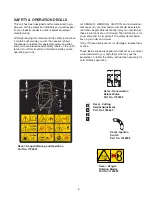
Page 7: ...messages on your rider and mower should be carefully read and obeyed Personal bodily injury can result when these instructions are not followed The information is for your safety and it is important The safety decals below are on your rider and mower If any of these decals are lost or damaged replace them at once These labels are easily applied and will act as a constant visual reminder to you and...

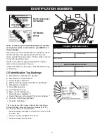
Page 8: ... of the identification tag in the manual S S A A M M P P L L E E S S A A M M P P L L E E North American CE Models CE Models Only CE Identification Tag Markings A Manufacturer s Identification Number B Manufacturer s Serial Number C Power Rating in Kilowatts D Maximum Engine Speed in Rotations per Minute E Manufacturer s Address F Year of Manufacture G CE Compliance Logo H Mass of Unit in Kilograms...

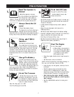
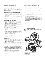
Page 9: ...set to the correct pres sures for optimum traction Rear Tire Pressure 10 12 PSI Front Tire Pressure 18 20 PSI 5 Push Unit Off Crate To push the unit off the crate Install wheels to axles see Setup Instructions Set BOTH transmission release levers to PUSH posi tion by pulling the levers back levers are located at the rear of the rider Cut the steel banding securing rider to pallet 6 bands Move the ...

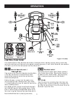
Page 10: ...e when mowing Move the lever forward to the detent for FULL throttle FAST Move the throttle back to decrease engine speed to IDLE SLOW Choke Close the choke for cold starting Open the choke once the engine starts A warm engine may not require chok ing Move the lever forward to close the choke Move the lever back to open the choke CONTROL FUNCTIONS The information below briefly describes the functi...

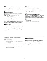
Page 11: ...the mower deck To turn the mower on pull the switch UP Push the switch DOWN to turn the mower off Note that the operator must be seated firmly in the rider seat for the PTO to function Transmission Release Levers The transmission release levers deactivate the transmis sions so that the unit can be pushed by hand See PUSHING THE UNIT BY HAND for operational informa tion Fuel Tank To remove the cap ...

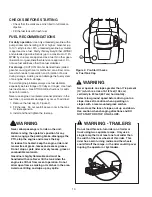
Page 12: ...r This rider has a zero turning radius and the wheels could fall off the ramps or the rider could tip over injuring the operator or bystanders WARNING TRAILERS CHECKS BEFORE STARTING Check that the crankcase oil is filled to full mark on dipstick Fill the fuel tank with fresh fuel FUEL RECOMMENDATIONS For daily operation Use only unleaded gasoline with a pump sticker octane rating of 87 or higher ...

Page 13: ...d engage the parking brake 2 Stop the mower by pushing down on the PTO switch 3 Move the throttle control to SLOW position and turn the ignition key to OFF Remove the key STARTING THE ENGINE 1 While sitting in the operator s seat make sure the PTO switch is OFF and the ground speed control levers are locked in PARK positions 2 Move the engine throttle control fully forward to FAST Set the choke co...

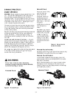
Page 14: ...t tire slippage and damage to your lawn We suggest you begin with the Smooth Travel procedure to the right and then advance through the forward reverse and turning maneuvers Forward Travel Practice Gradually move both ground speed control levers evenly FORWARD from neutral Slow down and repeat Reverse Travel Practice LOOK DOWN BEHIND then gradually move both ground speed control levers evenly BACK...

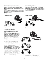
Page 15: ...me more familiar and experi enced with operating the zero turn rider you will learn more maneuvers that will make your mowing time easier and more enjoyable Remember the more you practice the bet ter your control of the rider will be Practice Turning Around a Corner While traveling forward allow one handle to gradually return back toward neutral Practice several times before mowing NOTE To prevent...

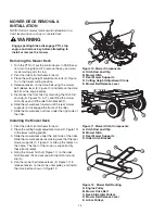
Page 16: ...heels forward 2 Place the cutting height adjustment crank D Figure 10 in the lowest cutting position 3 Slide the mower deck under the right side of the rider Slide the mower backwards making sure that the rear mower supports C Figure 11 slide up the ramps on the frame The rear of the mower is supported by these frame ramps 4 Hang the mower hitch B Figure 11 on the rider hitch bracket D and secure ...

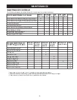
Page 17: ...rs 200 Hours Yearly Clean Debris from Rider and Engine Compartment Clean Debris from Engine Cooling Areas Air Filter Check Tire Pressure Lubricate Rider Mower Clean Deck Check Replace Mower Blades Clean Battery Cables Check Rider Safety System Check Adjust PTO Clutch ENGINE MAINTENANCE 18 5HP Briggs Stratton 8 Hours or Daily 25 Hours or Every Season 50 Hours or Every Season 100 Hours or Every Seas...

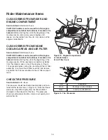
Page 18: ... unit at the beginning of the mowing session lift the seat deck and clean any debris from the intake screen on top of the engine A Figure 13 exposed engine cooling fins and around the air filter assembly Also open the air filter cover B and remove any debris that has accumulated in the air filter compart ment CHECK TIRE PRESSURE Service Interval 25 Hours Tire pressure should be checked periodicall...

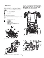
Page 19: ...el grease fittings front wheel bushings mower pivots mower arbors Use grease fittings when present Not all greases are compatible Use automotive type lithi um grease Oil rear frame assembly pivot hydro linkage brake linkage frame pivot points mower deck height adjustment linkage brake linkage Generally all moving metal parts should be oiled where contact is made with other parts Keep oil and greas...

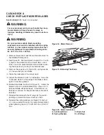
Page 20: ...balanced blade will remain level If the blade is not balanced continue to sharpen the heavy side until it balances 7 Reinstall the blade with the lift wings D Figure 20 pointing up toward the mower deck as shown 8 Reinstall the spring washers B Figure 20 and nut C Use a wooden block A to prevent blade rotation while tightening the nut C to 80 90 ft lbs 108 122 Nm WARNING For your personal safety d...

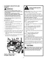
Page 21: ... be turned OFF and the ground speed control levers must be locked in their PARK positions in order to start the engine WARNING If the unit does not pass a safety test do not operate it See an authorized Dealer Under no circumstance should you attempt to defeat the purpose of the safety interlock system CLEANING THE BATTERY AND CABLES Service Interval 100 Hours 1 Disconnect the cables from the batt...

Page 22: ...ent nuts B Figure 22 until the rotor face and armature face just contacts the gauge 5 Check the windows for an equal amount of tension when the gauge is inserted and removed and make any necessary adjustments by tightening or loosen ing the adjustment nuts NOTE The actual air gap between the rotor and arma ture may vary even after performing the adjustment pro cedure This is due to dimensional var...

Page 23: ...er change NOTE Change engine oil while the engine is warm Run the engine for a few minutes then shut the engine off and allow it to cool from hot to warm 1 Clean the area around the dip stick C Figure 25 and oil drain tube A 2 Remove the oil drain plug A from the end of the oil drain tube Remove the dip stick C Allow ample time for complete drainage 3 Reinstall the oil drain plug A and route the h...

Page 24: ...m the cover 2 Remove the cover B Remove the filter C Figure 27 and pre cleaner D 3 Install the pre cleaner D with the mesh side up Install the filter C as shown 4 Install the cover B Figure 27 making sure the tabs are inserted into their slots Secure with the latch A 1 2 3 Figure 26 Air Filter Assembly Briggs Stratton Single Cylinder Models A Air Filter Latch B Air Filter Cover A B A B A B Figure ...

Page 25: ...80 in lbs 20 N m Figure 29 Spark Plug Gapping Pre Cleaner Service NOTE Replace a worn or damaged pre cleaner 1 Figure 28 Wash the pre cleaner in liquid detergent and water 2 Squeeze the pre cleaner dry and saturate with engine oil Remove all excess oil by squeezing the pre cleaner in an absorbent cloth Air Filter Service NOTE Replace a worn or damaged air filter 1 Figure 28 If stamped Washable the...

Page 26: ...Tighten the jam nut A to lock the carriage bolt in position To Adjust Operator Clearance The space between the operator and the control levers can be increase by removing the lower mounting bolt D Figure 30 pivoting the lever forward and reinstalling the capscrew through the control lever and forward slot C Repeat with the other ground speed lever SPEED BALANCING ADJUSTMENT If the rider veers to t...

Page 27: ...harging system or other electrical component If there is any doubt about the cause of the problem contact authorized Dealer If you need to replace the battery follow the steps under Cleaning the Battery Cables in the Regular Maintenance Section To charge the battery follow the instructions provided by the battery charger manufacturer as well as all warnings included in the safety rules sections of...

Page 28: ...ght to mid position Arrange the mower blades so that they are pointing from side to side Figure 34 5 Measure the distance between the tips of the outside blades and the ground Figures 33 34 If there is more than 1 8 3mm difference between the meas urements on each side proceed to step 6 If the dif ference is 1 8 3mm or less proceed to Front To Back Leveling 6 See Figure 35 Loosen the outside nut A...

Page 29: ...ng lock nut A against bracket MOWER BELT REPLACEMENT Mower Drive Belt Replacement 1 Park the rider on a level surface Disengage the PTO turn off the engine and set the ground speed control levers to PARK Remove the key 2 Use the idler pulley arm C Figure 38 to release belt tension and remove the mower drive belt A from the PTO pulley E 3 Remove the belt from the remaining deck pulleys Note It is n...

Page 30: ... prevent gum deposits from forming in the essential fuel system parts such as the carburetor fuel filter fuel line and fuel tank during storage Also alcohol blended fuels called gasohol or using ethanol or methanol can attract moisture which leads to the sepa ration and formation of acids during storage Acidic gas can damage the fuel system of an engine while in stor age To avoid engine problems u...

Page 31: ...choke to OPEN when engine is running A warm engine may not require choking Spark plug faulty fouled or incorrectly gapped Clean and gap or replace Engine knocks Low oil level Check add oil as required Using wrong grade oil See Change Engine Oil in the Maintenance Section Excessive oil consumption Engine running too hot Clean engine cooling fins blower screen and air cleaner Using wrong weight oil ...

Page 32: ... looking Engine speed too slow Always set throttle to FULL when mowing Ground speed too fast Decrease ground speed Blades are dull Sharpen or replace blades See Maintenance Section Mower drive belt slipping because it is oily or worn Clean or replace belt as necessary Blades not properly fastened to arbors See Check Replace Mower Blades in Maintenance Section Engine stalls easily with mower engage...

Page 33: ...an individual engine model are initially developed by starting with SAE Society of Automotive Engineers code J1940 Small Engine Power Torque Rating Procedure Revision 2002 05 Given both the wide array of products on which our engines are placed and the variety of environmental issues applicable to operating the equipment it may be that the engine you have purchased will not develop the rated horse...

Page 34: ......

Page 35: ......

Page 36: ...Box 997 Port Washington WI 53074 0997 www SimplicityMfg com PRODUCTS 535 Macon Street McDonough GA 30253 www Snapper com Briggs Stratton Yard Power Products Group Copyright 2006 Briggs Stratton Corporation Milwaukee WI USA All Rights Reserved ...

Reviews: