13
Basic Operation and Navigation
Controls and Indicators
3.2 Controls and Indicators
The external controls on the diagnostic tool are simple because most operations are controlled
through the touch screen. Touch screen navigation is menu driven, which allows you to quickly
locate the test, procedure, or data that you need through a series of choices and questions.
Detailed descriptions of the menu structures are found in the chapters for the various modules.
The following sections describe the external controls and features of the diagnostic tool.
3.2.1 Control Buttons
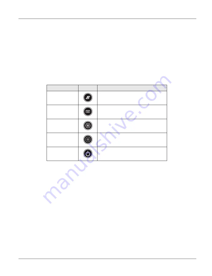
There are five control buttons located on the right side of the diagnostic tool near the handgrip:
All other diagnostic tool operations are controlled through the touch screen.
S (Shortcut) Button
Use the S Button to quickly capture an image of the current screen with a single button press. This
screen capture function is available at all times, even when operating outside of the VERUS
diagnostic tool software.
3.2.2 LEDs
The four light-emitting diodes indicate certain system conditions:
•
Hard Drive Activity LED—illuminates when the central processing unit (CPU) is reading or
writing to the hard disk drive (HDD).
•
Wireless LAN Activity LED—illuminates when a wireless local area network (LAN) in enabled,
flashes when data is being sent or received.
•
Battery Charging LED—illuminates when the internal battery pack is charging.
•
Main Power LED—illuminates when the diagnostic tool is powered on or in Standby mode.
Name
Button
Description
S (Shortcut) Button
A function button that provides a shortcut for
performing routine tasks.
Keyboard
Opens, and closes, a virtual keyboard on the
touch screen.
Brightness Up
Incrementally increases the screen
backlighting.
Brightness Down
Incrementally decreases the screen
backlighting.
Power
Turns the diagnostic tool on and off. Also, press
and hold for 5 seconds for emergency
shutdown.
Summary of Contents for VERUS
Page 1: ...User Manual EAZ0061B58A Rev E ...
Page 4: ...iv ...


