background image

Data Cable / Connections

Data Cable Connection (OBD-I Vehicles)

19

3.3   Data Cable Connection 

(OBD-I Vehicles)

For most OBD-I (non-OBD-II/EOBD) compliant vehicles you can use the supplied 
data cable with the optional DA-5 adapter, and an optional manufacturer specific 
OBD-I adapter(

Figure 3-4

). 

a. The 26-pin end “

A

” of the cable (

Figure 3-4

) connects to the diagnostic tool. 

b. The16-pin end “

B

” of the cable (

Figure 3-4

) connects to the DA-5 adapter 

C

”.

c. One end of the manufacturer specific adapter “

D

” (

Figure 3-4

) connects to 

the to the DA-5 adapter.

d. The other end of the manufacturer specific adapter “

E

” (

Figure 3-4

) connects 

to the vehicle. 

OBD-I adapters with a power jack MUST be connected to the vehicle battery 
using an accessory power cable “

F

” (

Figure 3-4

).

See 

Figure 3-5

 for additional information. 

If the OBD-I adapter does not have a power jack, an external power 
connection (accessory power cable) is not needed. 

Figure 3-4 

Figure 3-5

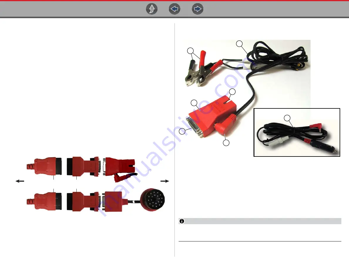
 shows a typical OBD-I adapter (with power jack). This type of adapter 

MUST be connected to the vehicle battery, using either of the power cables shown. 

Figure 3-5 

1— Connect Clamps to Vehicle Battery 
2— Accessory Power Cable (Battery clamp type)
3— Power Cable Connection
4— Connects to DA-5 Adapter
5— Typical OBD-I Adapter (with power jack)
6— Connects to Vehicle
7— Accessory Power Cable (Power port type)

NOTE

Only use original Snap-on data cables and accessories with your diagnostic 
tool. Total data cable length must not exceed 114.17 inches (2.9 meters). 

DA-4 Series Data Cable

DA-5 OBD-I Adapter

U.S. Domestic OBD-I

Typical - OBD-I Manufacturer 

Specific Adapter

(e.g. CHRY-1 shown)

To Diagnostic Tool

European OBD-I

Typical - OBD-I Manufacturer 

Specific Adapter

(e.g. BM-1B shown)

To Vehicle

A

A

B

B

C

C

D

D

E

E

(e.g. C

E

F

B

5

2

7

4

6

1

3

Summary of Contents for TRITON-D10

Page 1: ...User Manual Start BC ...

Page 2: ...ta Cable Connections 17 About Ethernet Equipped Vehicles and Data Cables 17 Data Cable Connection OBD II EOBD Vehicles 17 Data Cable Connection OBD I Vehicles 19 Optional OBD I Data Cables and Adapters 20 Section 4 Scanner 21 Quick Links 21 General Information 21 Scanner Control Icons 21 Secured Vehicle Gateway 22 Quick Access Menu 22 Vehicle Voltage Readout 22 Basic Operations 23 Scanner Overview...

Page 3: ...n Layout and Icons 64 Screen Layout 64 Guided Component Tests Control Icons 65 Operation 65 Component Information 66 Tests 67 Saving and Reviewing Data Files 69 Section 9 Scope Multimeter 70 Safety Information 70 Measurement Out of Range Indicator 70 Overview 71 Digital Multimeter DMM 71 Graphing Multimeter GMM 72 Lab Scope 73 Tests and Capabilities Quick Reference 74 Test Leads and Accessories 75...

Page 4: ...Global OBD II Code Check 118 Global OBD II Clear Codes 118 Readiness Monitors 119 MIL Status 119 Section 12 Previous Vehicles and Data 120 Vehicle History 120 Saved Data 121 Viewing Printing Saved Codes and Code Scan Results 121 Delete Saved Data 121 Section 13 Tools 122 Tools Main Menu 122 Connect to PC File Transfer 123 Get Connected 123 Configure Shortcut Key 123 System Information 123 Software...

Page 5: ...ds and test procedures It is important to perform tests in an appropriate and acceptable manner that does not endanger your safety the safety of others in the work area the equipment being used or the vehicle being tested It is assumed that the operator has a thorough understanding of vehicle systems before using this product Understanding of these system principles and operating theories is neces...

Page 6: ...al hazard Safety Message Example Risk of electric shock Prior to recycling the battery pack protect exposed terminals with heavy insulating tape to prevent shorting Disconnect all test leads and turn diagnostic tools off before removing the battery pack Do not attempt to disassemble the battery or remove any component projecting from or protecting the battery terminals Do not expose the diagnostic...

Page 7: ...tion United States registration snapon com products us Canada registration snapon com products ca ShopStream Connect snapon com diagnostics us SSC Snap on Cloud altusdrive com SureTrack Community Use ShopKeyPro com or ProDemand com SureTrack Login Info www mitchell1 com micro stc Secure Vehicle Gateway www snapon com gateway Training Solutions Videos snapon com diagnostics US CC YouTube ShopKey Pr...

Page 8: ...the latest information is included Download the latest version of this manual and other related technical documentation from the product website see Customer Support Links on page vii 1 2 Serial Number Software Version The diagnostic tool serial number and software version can be viewed from Home Tools System Information see System Information on page 123 The diagnostic tool serial number is also ...

Page 9: ...e tool off NOTE An optional power cable is required when testing non OBD II EOBD or models that do not supply power on the DLC IMPORTANT Never connect the AC power supply adapter or optional power cable to the diagnostic tool when communicating with a vehicle IMPORTANT All vehicle communication must be stopped BEFORE turning off the diagnostic tool Never disconnect the Data Cable when the diagnost...

Page 10: ...D Card contains operating system programming IMPORTANT The uSD card must be installed for operation Do not remove the uSD card while the diagnostic tool is powered on 6 Data Cable Connector 7 No Cancel Button Yes Accept Button Directional Control Buttons Tip These buttons can be used for general navigation however are especially useful in certain situations where more control is needed compared to...

Page 11: ...ink connector voltage 2 Active vehicle communication status 3 Wi Fi connection status 4 Time of day 5 Battery charge level and power connection status Figure 1 2 Home Screen Icons Links 1 2 3 4 5 13 7 V 13 7 V Scanner OBD II EOBD Guided Component Tests Scope Multimeter Quick Lookups Previous Vehicles and Data Training and Support Tools ...

Page 12: ...ata OBD IIEOBD to Scanner to check enhanced codes and access Fast Track Intelligent Diagnostics Scanner to Exit Vehicle to quickly Exit vehicle communication Scanner to Tools to change display settings turn Wi Fi on configure the Shortcut button or connect to a PC Figure 1 3 1 9 Printing Reports Screenshots and Data Use the Snap on Cloud and ShopStream Connect to print reports screenshots and data...

Page 13: ...ou to set arm and clear PID triggers Change View Toggle data display between list or graph Zoom Incrementally increases and decreases the scale of the data displayed Lock Locks PIDs to the top of the list Step Forward Allows forward movement in singular steps Note To quickly step forward during Scanner data review press and hold Step Back Allows backward movement in singular steps Note To quickly ...

Page 14: ...on Zoom Increases and decreases screen magnification The zoom function is only available during data review scope paused Expand Collapse Toggles display of the control panel Trace Detail Cursors Toggles cursors on off Save Saves the data stored in buffer memory to a file Step Forward moves to the next point in the data To quickly step forward select this icon then press and hold the Y a button Too...

Page 15: ...tery pack Do not heat the battery pack to over 100 C 212 F or dispose of it in a fire Do not expose the battery pack to excessive physical shock or vibration Keep the battery pack out of reach of children Do not use a battery pack that appears to have suffered abuse or damage Charge the battery pack in the appropriate charger only Do not use a battery charger that has been modified or damaged Use ...

Page 16: ...harge the battery pack Insert the end of the AC power supply cable into the diagnostic too power supply jack then connect the AC power supply to an approved AC power source IMPORTANT Only use the supplied AC power supply Never connect the power supply to the diagnostic tool when the tool is communicating with a vehicle The Battery Status Indicator LED located next to the power supply jack indicate...

Page 17: ...le Battery Recycling Corporation RBRC at www call2recycle ca Phone 888 224 9764 Products bearing the WEEE logo Figure 1 6 are subject to European Union regulations Figure 1 6 Contact your sales representative for details 1 13 Care and Cleaning Periodically perform the following tasks to keep your diagnostic tool in proper working order Check the housing cables and connectors for dirt and damage be...

Page 18: ...Quick Tips Videos examples Air Fuel Ratio Sensor Test Fuel Injector Voltage and Current Tests Scope Alternator Ripple Test Scope Fuel Pump Current Ramp Test Scope BMW Rain Sensor Calibration Harley Davidson ABS Brake Bleed CAN Bus Diagnostics Scope Harley Davidson Functional Tests Chevrolet Volt Coolant Pump Bleed Harley Davidson Key Fob Programming Chrysler HVAC Test Hyundai Blind Spot Detection ...

Page 19: ...ming The Power of Troubleshooter Tips Scanner Ford 6 7L Transmission Solenoid Characterization Top Level Menus Built In Scope Training Ford Diesel Injector Coding Toyota EVAP Test VW Audi Flexible Service Reset Scanner Toyota Multiple Freeze Frame Scanner Toyota Transmission Compensation Coding Snap on Training Solutions Diagnostic Quick Tips Videos examples Snap on Training Solutions Training Vid...

Page 20: ...7 The Snap on Cloud is a free mobile friendly cloud based application designed specifically for technicians to store organize and share information Typical screens shown in Figure 2 1 and Figure 2 2 Key Features Diagnostic tool automatically transfers code scan reports ADAS reports and screen captures to the Snap on Cloud Access and manage your Snap on Cloud account using your mobile device or PC ...

Page 21: ...quires USB connection of the diagnostic tool to a personal computer with Internet access ShopStream Connect is a free PC application that allows you to Transfer print and edit select fields the Code Scan Vehicle System Report Transfer and print data files and screenshots View save and manage data files on your PC Add or edit notes and comments to your data files To Get ShopStream Connect SSC 1 Dow...

Page 22: ...Companion Applications ShopStream Connect Connecting to your PC 15 Figure 2 4 Figure 2 5 ...

Page 23: ...et access via computer or mobile device Your diagnostic tool may include authorization to access to the online SureTrack Community You can use your PC to access the latest Real Fixes Related Tips and Common Repair Procedures information SureTrack is an evolving database of real world automotive repair knowledge based on expert knowledge and millions of actual repair orders Typical login screen sho...

Page 24: ...vehicles In order to communicate via Ethernet the data cable supplied with this tool marked DA 4E must be used Substituting a different data cable may result in no or an erroneous communication condition 3 2 Data Cable Connection OBD II EOBD Vehicles IMPORTANT Only use the supplied data cable and or original equipment accessory cables with your diagnostic tool Total data cable length must not exce...

Page 25: ...flashlight is powered by the diagnostic tool battery and is useful when locating the vehicle DLC Figure 3 2 2 Connect the 16 pin J 1962 end of DA 4E cable Figure 3 3 to the vehicle DLC Figure 3 3 NOTE During vehicle identification on screen cable connection instructions may be provided along with the location of the DLC 2 1 3 4 5 6 7 8 10 9 11 12 13 14 15 16 J 1962 DA 4E ...

Page 26: ...nal information If the OBD I adapter does not have a power jack an external power connection accessory power cable is not needed Figure 3 4 Figure 3 5 shows a typical OBD I adapter with power jack This type of adapter MUST be connected to the vehicle battery using either of the power cables shown Figure 3 5 1 Connect Clamps to Vehicle Battery 2 Accessory Power Cable Battery clamp type 3 Power Cabl...

Page 27: ...turer specific OBD I adapter This may be used instead of the optional DA 5 adapter An optional U S domestic and Asian vehicle OBD I adapter kit is available for select vehicles The kit includes multiple manufacturer specific adapters and cables for OBD I connection An optional European vehicle OBD I adapter kit is available for select vehicles The kit includes multiple manufacturer specific adapte...

Page 28: ...e 33 Using Zoom page 36 Using Triggers page 36 Functional Tests page 39 Troubleshooter page 40 4 2 General Information 4 2 1 Scanner Control Icons Icon Function Icon Function Pause Pauses active data collection Start Capture Resumes active data collection Clear Erases all the PID data in the buffer and restarts data collection Custom Data List Allows you to choose which PIDs display Trigger Allows...

Page 29: ... Access Menu on page 5 Figure 4 1 4 2 4 Vehicle Voltage Readout When the data cable is connected to the vehicle the vehicle s battery voltage at the data link connector is displayed on the top of the screen Figure 4 2 Diagnose Opens Fast Track Intelligent Diagnostics for the selected code Save Saves the active information to memory Automatic ID Automatically completes the identification process on...

Page 30: ...ptions and procedures vary by vehicle Not all vehicles support Auto ID and or Instant ID Depending on the vehicle the vehicle identification process may require manual entry of the vehicle information or it may be automated The following functions are available to identify the vehicle Instant ID See Instant ID on page 24 for additional information Manual ID Allows for manual entry of all required ...

Page 31: ...An audible beep will sound approximately 6 seconds after boot up if the VIN is read 3 Vehicle identification confirmation displays select Ok to continue NOTE If the Scanner feature is exited during the session that Instant ID was used selecting Scanner again will not automatically ID the vehicle again However you can select the Automatic ID Icon to restart the identification As an alternate method...

Page 32: ...egorized and non categorized list view Select a system test option as applicable NOTE Only the systems test options supported for the vehicle are displayed Figure 4 4 Once a system test option is selected the available options for that system are displayed in the System Main Menu Figure 4 5 Navigation Home Screen Typical Scanner Vehicle Identification Vehicle System Menu Vehicle System Main Menu S...

Page 33: ...ble codes select Codes Menu and then make any sub menu selections as applicable if available Depending on the vehicle manufacturer the Codes Menu and sub menu selection names will vary e g Codes Codes Menu Codes Only Codes No Data Service Codes Display Codes etc 4 4 3 Display Codes Navigation Home Screen Typical Scanner Vehicle Identification Vehicle System Menu Vehicle System Main Menu Codes Menu...

Page 34: ...Freeze Frame icon Figure 4 7 displays the corresponding Freeze Frame data that was captured when the code was set Figure 4 7 4 4 5 Clear Codes Navigation Home Screen Scanner Vehicle Identification Vehicle System Menu Vehicle System Main Menu Clear Codes Clear Codes allows you to erase codes from ECM memory IMPORTANT Clearing codes erases all temporary ECM information including Freeze Frame Failure...

Page 35: ... and relearns supported for the vehicle Figure 4 8 Selecting Service Resets and Relearns from the System menu Figure 4 8 opens a categorized list of all the available resets and relearns Figure 4 9 Figure 4 9 Making a selection from the menu Figure 4 9 opens the related information screen for that specific Reset Relearn Figure 4 10 The information provided may include Top Repairs Graph Shows the t...

Page 36: ...lay all available PIDs for that system As an example from within an Engine system Data menu the Engine Data option can be used to display all Engine related PIDs Related System Data display a list of PIDs that are related to the primary system e g Misfire EVAP and Fuel Trim PID lists are related to the Engine system Custom Data user defined list of PIDs see Custom Data Lists on page 29 4 6 2 Custo...

Page 37: ...its that only operate in two modes or states e g solenoids relays and switches that are either open closed on off true false etc To set two state PID Indicators select the PID Alarm icon Choose the PIDs indicators to display Figure 4 15 then select the Back arrow PID indicators are displayed in the data list Figure 4 16 and change color as the states change Figure 4 15 Figure 4 16 ...

Page 38: ...y the next data list when more than one list is available Figure 4 17 In graph view the text block Figure 4 18 to the left of the graph displays Top PID description Middle Current value or state Bottom Active minimum and maximum values Figure 4 18 4 6 5 Locking PIDs to always display at top Use the Lock icon to lock selected PIDs at the top of the list To lock or unlock a PID highlight the paramet...

Page 39: ... reviewed using the toolbar controls Figure 4 20 1 Data Buffer Scale Displays maximum data buffer size e g 4000 across screen 2 Data Buffer Indicator Bar graph indicates total data stored in the memory buffer Includes blue and white graph bars and active position indicator 3 Blue Graph Bar Stored data not displayed onscreen 4 White Graph Bar Stored data displayed onscreen 5 Active Data Position Co...

Page 40: ...ext to the scroll bar making it difficult to see If this happens use the control icons Step Skip to move the data until you can see the cursor Red Triggered PID Activation Point When using triggers a vertical red cursor is displayed in the data of the triggered PID at the point where the trigger was activated When multiple PIDs are armed only the PID that is triggered first will display a red curs...

Page 41: ...ill be used for each instance Figure 4 24 4 6 9 Saving Data Files Saving data is useful when trying to isolate an intermittent problem or to verify a repair During normal operation data from the vehicle is continuously being stored in buffer memory as it is displayed onscreen Selecting the Save icon writes stored buffer memory to a SCM file NOTE The Save icon performs the same function as Save Mov...

Page 42: ...25 indicates your position in the data and is denoted by the current position value Figure 4 25 in the counter display The cursor displays in all PIDs Depending on the amount of data saved the cursor may be initially located on the far left next to the description or the far right next to the scroll bar making it difficult to see If this happens use the control icons to move the data until you can...

Page 43: ... be collected on one screen The default magnification level is 1x Examples Figure 4 26 Top 4X Middle 1X Bottom Zoom Out Figure 4 26 4 6 12 Using Triggers Trigger Description and Features Setting PID triggers allows you to configure the diagnostic tool to automatically save PID data to a file when a PID value meets an upper lower limit trigger point When a PID value meets the trigger point it activ...

Page 44: ...tivated 6 Trigger Activation Point Reference Cursor Green cursors lines are displayed on all the other PID graphs to indicate their relationship to where the trigger occurred PID Trigger Status Icons The icons below are used to help you quickly identify the status of individual PID triggers z Setting triggers To use triggers they must be turned on set configured and then armed Use the following pr...

Page 45: ...ion of the upper trigger point 5 Select a or press the Y a button to set the upper trigger point Figure 4 29 The upper trigger line changes color to gray and the lower trigger line displays in red Figure 4 30 6 Change the position of the lower trigger line in the same manner as the upper 7 When finished select a or press the Y a button to set the lower trigger level Figure 4 30 The display returns...

Page 46: ...ger to indicate where the trigger occurred A green cursor line is displayed on all the other PID graphs to indicate their relationship to where the trigger occurred The trigger menu options are Clear Trigger deletes the highlighted trigger Arm Trigger arms the trigger to capture data Clear All Triggers deletes all set triggers Figure 4 33 4 7 Functional Tests Navigation Home Screen Scanner Vehicle...

Page 47: ...ot available for all vehicles Troubleshooter provides reference information from actual repairs Code tips parameter descriptions along with repair guidelines are some of the information that may be included Typical information Code Tips provides detailed information on setting conditions testing and interpreting test results for specific codes Symptom Tips provides diagnostic tests and procedures ...

Page 48: ...0 Tire Pressure Monitor Codes 3 OBDII 0 Body Control Module Codes C1704 Low Pressure Left Front C1706 Low Pressure Right Rear C1707 Low Pressure Left Rear Tire Pressure Monitor Codes C1704 Low Pressure Left Front C1706 Low Pressure Right Rear C1707 Low Pressure Left Rear READINESS MONITORS Tests Complete Misfire Fuel System Comprehensive Component EGR VVT Catalyst Evaporative System Oxygen Sensor ...

Page 49: ...and then displays the results Figure 5 4 Figure 5 4 Code Scan result descriptions are provided in the following sections After the code scan has competed it is automatically saved as an XML file on the diagnostic tool and is uploaded to your Snap on Cloud account To view the report on the diagnostic tool see Viewing Printing Saved Codes and Code Scan Results on page 121 To view print the report on...

Page 50: ...o view the main menu for a system in the list select the system or select the System icon Figure 5 6 Figure 5 6 Code Scan Icons Refresh Refreshes restarts the code scan System Opens the main menu of the system selected highlighted Diagnose Opens Fast Track Intelligent Diagnostics for the code selected highlighted Save Saves the code scan results as an XML file See Viewing Printing Saved Codes and ...

Page 51: ...Code Scan list A message will be displayed to inform you the OBD II codes and monitors for this vehicle may be accessed using the global OBD II function See OBD II EOBD on page 113 5 1 4 Readiness Monitor Test Status At the end of the Code Scan list readiness monitor test results are displayed as Tests Complete or Not Complete Quick reference indicators are used to show monitor status Green icon a...

Page 52: ...oud on page 13 NOTE Code scan reports are automatically saved each time a code scan is performed The report is automatically uploaded to your Snap on Cloud account if registered and Wi Fi is connected The code scan vehicle system report includes Basic vehicle information A list of the code scan results by system Individual system DTCs with a brief description Global OBD codes Readiness monitor tes...

Page 53: ... addition you can directly access all not just code related PIDs and functional tests from one place as compared to accessing them separately through the individual system menus Wi Fi Required Wi Fi connection is required to use this application See Wi Fi Connection Troubleshooting on page 127 6 1 Demonstration Selecting the Help icon Figure 6 1 starts a Fast Track Intelligent Diagnostics slidesho...

Page 54: ...reen Scanner Vehicle Identification Vehicle System Menu Vehicle System Main Menu Codes Menu Code Results Diagnose Icon Fast Track Intelligent Diagnostics may also be accessed when viewing codes in Code Scan or in individual systems Figure 6 3 6 3 Main Menu Fast Track Intelligent Diagnostics functions are contained in a common multi card main menu Figure 6 4 Card functions are described in the foll...

Page 55: ...ation about that code within Fast Track Intelligent Diagnostics Figure 6 6 6 6 Top Repairs Graph The Top Repairs Graph Figure 6 7 shows the most common verified fixes and procedures for the selected code Example In the graph shown below the most common fix for the code was replacing the intake manifold gasket This fix occurred 413 times with the most occurrences 85 at 100k miles in vehicles with u...

Page 56: ...quick link to available OEM Recall TSB and Campaign information that is code related A red icon Figure 6 10 indicates the total number of Recalls TSBs and OEM Campaigns that have been found Green check mark indicates no TSS s were found Figure 6 10 Select a topic from the list Figure 6 11 to view detailed information on the topic Figure 6 12 Figure 6 11 Figure 6 12 ...

Page 57: ...s all not just code related PIDs from one place as compared to accessing them separately through the individual system menus IMPORTANT Smart Data works best when the vehicle is idling at operating temperature with no load present Always refer to OEM service information for specific PID range limit information Figure 6 13 PID List View Figure 6 14 Figure 6 14 PID Graph View Figure 6 15 Figure 6 15 ...

Page 58: ... Smart Data values Note Manually set triggers will display upper and lower trigger limit lines in the graph When a trigger is activated Data collection continues briefly after the trigger point then pauses as the Scanner captures a recording of the data Data is saved leading up to and just past the trigger point An audible alarm is sounded A message displays indicating a data file was saved Data c...

Page 59: ...set options related to the selected code The lower list may provide additional Functional Tests and Reset options that are not code related but are vehicle specific and may be useful in troubleshooting or validating repairs Figure 6 19 6 10 Real Fixes The Real Fix displayed on the Main Menu Figure 6 20 is the most common to date The information is displayed in a Complaint Cause Correction format F...

Page 60: ...ooter Figure 6 25 provides a list of available code related tips gathered from industry professionals NOTE Troubleshooter Tips may not be available for every vehicle and or DTC Figure 6 24 Select a Related Tip from the list Figure 6 25 to view the information Figure 6 26 Figure 6 25 Figure 6 26 ...

Page 61: ...ormation Scanner Functional Resets NOTES Oil Specs and Resets vehicle coverage is the same as the Scanner vehicle coverage Not all vehicles may have on board diagnostic tool reset capabilities or have information available To use the Oil Specs and Resets feature you must have authorized access contact your sales representative for details The diagnostic tool is equipped with the ability to connect...

Page 62: ... Follow the screen prompts to ID the vehicle then select an option Perform a service interval reset using the diagnostic tool View OEM service reset instructions and related information Figure 7 1 7 1 2 Fluid Capacity Selecting the Fluid Capacity icon displays OEM recommended engine oil and capacity information Figure 7 2 Typical information may include Vehicle application information Oil capacity...

Page 63: ...t menus and selections will vary by manufacturer 1 Select the Functional Reset icon 2 Select the applicable menu option s to perform the functional reset 3 Read and perform any instructions that are provided 4 If applicable once the reset has completed select OK or Continue The following screen examples Figure 7 3 illustrate typical indicator reset screens Figure 7 3 7 1 4 Reset Procedure Selectin...

Page 64: ...Service vehicle coverage is the same as the Scanner vehicle coverage Not all vehicles may have on board diagnostic tool reset capabilities or have information available To use the Tire and Wheel Service feature you must have authorized access contact your sales representative for details The diagnostic tool is equipped with the ability to connect to a Wi Fi network however the connection is solely...

Page 65: ...he System menu Figure 7 5 Follow the screen prompts to ID the vehicle then select an option Figure 7 5 TPMS Indicator Reset Selecting the TPMS Indicator Reset icon displays TPMS indicator reset instructions Typical information may include Instructions for manually resetting the TPMS indicator using on board vehicle functionality Special notes and or instructions Theory of operation The following e...

Page 66: ...lear Codes View Data Perform TPMS Related Functional Tests Resets View TPMS Troubleshooter Information IMPORTANT Functional test instructions may be provided that are required to be performed before selecting or completing the function itself Follow all instructions as written NOTES Scanner functions require connection and communication with the vehicle Functional tests resets are not available fo...

Page 67: ...gure 7 8 Tire Wheel Specifications Fitment Selecting Tire Wheel Specifications displays OEM tire and wheel specifications Figure 7 9 Typical information may include Tire size and pressure Wheel hub stud size and lug torque Wheel size Figure 7 9 ...

Page 68: ...ning and Classes feature provides even more support by including non vehicle specific tests and resources that allow you to quickly perform common tests review basic reference information and more Main Topic Links Training and Classes page 61 Screen Layout and Icons page 64 Operation page 65 Component Information page 66 Tests page 67 Saving and Reviewing Data Files page 69 8 1 Training and Classe...

Page 69: ...tage and current Transducers are available as optional equipment A T Line Pressure and Shift Solenoid A T Line Pressure Test EGR Temperature Sensor and EGR Vacuum Exhaust Back Pressure Test Fuel Pressure and Fuel Pump Current and Voltage Fuel Pressure Test 8 1 2 Features and Benefits Navigation Home Screen Guided Component Tests Training and Classes Features and Benefits Selecting Features and Ben...

Page 70: ...t testing No Start Basics provides basic step by step procedures for the diagnosis of a no start condition on carbureted and fuel injected vehicles O2 Sensor Feedback System Analysis provides basic definition and theory information for the following O2 sensor topics Air Fuel Ratio Sensors Correct PCM Response includes configured meter test Heated Oxygen Sensor Non Heated Oxygen Sensor Open and Clo...

Page 71: ...urrent Ramp multiple types Fuel Pump Current Ramp Fuel Pump RPM Calculation Ignition Coil Current Ramp multiple types Parasitic Draw Snap on Low Amp Probe Reference Manual Using Fuse Box for Current Test Hard to Reach Wiring 8 2 Screen Layout and Icons This section describes the Guided Component Tests control icon functions and screen layout 8 2 1 Screen Layout 1 Vehicle Identification 2 Toolbar c...

Page 72: ... test Other control icons not shown are described in Icon Reference Table on page 6 8 3 Operation As the information and tests provided within the Guided Component Test function is vehicle specific the vehicle must first be identified in order to retrieve the correct data z To identify a vehicle The vehicle identification process is the same as the process used for the Scanner function see Vehicle...

Page 73: ...rmation provides identification of components connector pin location and functions and abbreviation reference 8 3 1 Component Information Component Information provides if available specific operational information on the selected component and may also include electrical connector and pin location and function details z To view component information 1 Select a component 2 Select Component Informa...

Page 74: ...s if available Use the scroll bar to view additional information 3 Select Back on the Toolbar or press the N X button to return to the component menu 8 3 2 Tests Tests provides if available specific instructions to help you perform tests on components Selecting a component test opens a preconfigured meter to start the test and may also provide connection instructions specifications and testing tip...

Page 75: ...plays Figure 8 8 Use the scrollbar to display hidden information 3 Select View Meter to display the meter display and to perform the test Figure 8 8 4 Use the Expand Collapse icon to toggle through split and full screen views and to display the control panel Figure 8 9 Figure 8 9 ...

Page 76: ...the component tests However if the need to change channel settings is needed adjustments can be made by using the Control Panel Figure 8 11 To access the Control Panel use the Expand Collapse icon to toggle the view For additional information on channel settings see Control Panel and Settings on page 81 Figure 8 11 8 3 3 Saving and Reviewing Data Files Save and Stop control icon operation and data...

Page 77: ...pulse is 500 volts DO NOT exceed the rated transient over voltage Risk of electrical shock Read the Safety Information provided for important warnings on the use of this product This product is intended for Measurement Category I for example automotive 12V systems do not use this product for Measurement Categories II III and IV Measurement Category I is for performing measurements on circuits not ...

Page 78: ...igital multimeter gives you the ability to quickly make precise common electrical measurements e g DC and AC voltage resistance and amperage on circuits and components to verify operation The meter displays measurements in a digital numerical format and is typically used for measuring signals that are not rapidly changing The DMM is ideal for performing basic tests on most standard automotive circ...

Page 79: ...ed to the lab scope sweep scales that use relatively short time intervals e g milli and micro seconds This allows you to monitor a signal over a longer period of time when looking for erratic glitches or dropouts To use the GMM select the Scope Multimeter icon from the home screen then select Graphing Multimeter from the menu See Tests and Capabilities Quick Reference on page 74 for a list of avai...

Page 80: ...hen performing diagnostics To use the lab scope select the Scope Multimeter icon from the home screen then select Lab Scope from the menu See Tests and Capabilities Quick Reference on page 74 for a list of available testing functions Specifications Function Range Accuracy Comments Signal Measurement Ch 1 yellow jack Ch 2 green jack Each channel input is referenced to common ground GND black jack S...

Page 81: ... DC current is passed through the diode to measure the voltage drop between the two connected test leads Typical setup for positive to negative current flow positive lead anode side and negative cathode side a Frequency Measures the number of times a signal repeats itself per second Used to measure frequency of signals such as CKP CMP and wheel speed sensors a Pulse Width Measures the on time of v...

Page 82: ...lly connected to the standard ground lead therefore it does not need to be connected to the diagnostic tool ground jack 9 4 2 Channel 2 Lead The shielded green lead is used with channel 2 and is color matched with the channel 2 jack on the diagnostic tool This lead also includes a black right angle stackable ground plug Figure 9 3 Green Channel 2 lead a a 100 PSI Pressure Used to measure pressures...

Page 83: ...gle stackable ground plug and a RCA type connector that is used to connect the lead to a secondary ignition adapter The spring clamp is used to connect to a ground Figure 9 5 Secondary Ignition Coil Adapter Lead and Clip on Wire Adapter NOTE Contact your sales representative for additional information on OEM specific CIC and COP secondary ignition adapters 9 4 5 Low Amp Current Probe optional The ...

Page 84: ...tional waveform demonstration tools are available as a training aid These demonstration tools generate common waveforms and allow you to vary their display characteristics by turning glitches on off helping you to become more familiar with the lab scope controls Common waveforms include AC sine wave variable frequency and pulse secondary ignition and more There are two tools currently available th...

Page 85: ...ification is not required NOTE Images and screenshots in the following sections are provided as general reference only and in some instances have been modified for clarity 9 5 1 Scope Multimeter Screen Layout and Features 1 Toolbar contains navigational and control icons 2 Main Body contains the meter scope display 3 Control Panel contains channel trace controls 4 Data Buffer Position Indicators g...

Page 86: ... of the of stored buffer data during saving and playback For additional information on the Data Buffer Data Buffer Position Indicator and Saving Storing and Reviewing Data files see About the Data Buffer on page 97 Icon Function Pause Pauses the data buffer Start Capture Resumes active data collection Zoom Increases and decreases screen magnification The zoom function is only available during data...

Page 87: ...heir jacks Pull only on the lead terminal end 1 Ground Jack Black 2 Channel 1 Jack Yellow 3 Channel 2 Jack Green Figure 9 11 9 6 2 Test Lead Probe Calibration Certain tests may display a confirmation prompt asking Do you wish to calibrate this probe before continuing with the test As general practice it is important to ensure the test probe is calibrated before testing to ensure accurate results T...

Page 88: ...nded as a general overview of the channel settings Not all the settings or controls described in this section are applicable with all functions some may be grayed out or not active applicable depending on the function or test Function availability is noted as applicable NOTE The control panel can be toggled on off by selecting the Expand Collapse Icon to switch the screen between full and split te...

Page 89: ...e etc and the unit of measurement it is being measured in The vertical scale is always divided into10 major divisions how these divisions are defined sets the scale of measurement NOTE Vertical scales either channel can be set independently NOTE Optional vertical scale preference settings are available The Divisions option allow you to change to your preference how the vertical scale menu selectio...

Page 90: ...efined sets the scale of measurement The value displayed in the sweep Scale icon indicates the active sweep setting NOTE The sweep setting applies to all channels and cannot be set independently per channel To adjust the sweep scale unit of measurement value select the Sweep Scale icon to open the sweep scale menu Select a value then press the N X button to exit the menu 1 Sweep Scale 2 Sweep Scal...

Page 91: ...n see Test Lead Probe Calibration on page 80 Probe test Options Menu Option Probe Device Used Test Lead Volts DC Standard Channel 1 and 2 test leads with alligator clips or test probes Vacuum 100 optional 0 100 psi pressure transducer with pressure adapter Pressure 100 Pressure 500 optional 0 500 psi pressure transducer with pressure adapter Pressure 5000 optional 0 5000 psi pressure transducer wi...

Page 92: ...ing rate 5 Filter removes signal noise or interference 6 Invert switches signal polarity 7 Coupling AC blocks the DC portion of signal 8 Scale Vertical scale adjustment adjusts vertical scale 9 Trigger turns triggering on off and sets direction of trigger slope 10 Refresh clears Min Max and Live values and resets to zero 11 Min Live and Max Display Panel displays lowest highest and current trace m...

Page 93: ...r memory to plot a waveform across the screen No preference is given to any point during the selection process NOTES Turning peak detect off is suitable for basic measurements and viewing waveforms e g oxygen O2 or Cam sensor when capturing fast events is not necessary The longer the time sweep the greater the chance a glitch could be missed because it occurred in between the sample points saved t...

Page 94: ...w voltage scale is used to measure the output of the probe due to the conversion factors of the probe Example For a probe with a conversion factor of 100 mV A connected to a 2 amp load the scope uses a 200 mV scale to measure the output of the probe The scope converts the measured output to 2 amps for display on the screen Filter GMM Using the filter with the GMM the filter minimizes noise by igno...

Page 95: ...ons crosses the trigger point the trace will start Trigger conditions Vertical scale position amplitude Sweep position the horizontal scale position or position in time Slope direction the direction the trace must be moving up rising or positive or down falling or negative when crossing the trigger point NOTES Triggers can be set on any channel however only one trigger can be activated used at a t...

Page 96: ... trigger marker select and drag it into position using the touch screen 4 To more accurately position the trigger marker select the Trigger Position Control icon Figure 9 22 The trigger position control panel opens 5 Use the directional controls provided or the thumbpad directional controls to move the trigger marker into position Figure 9 21 Sweep and vertical scale values are provided in the tri...

Page 97: ...Select the Settings icon from the toolbar Navigation Home Screen Settings Configure Scope Meter Trigger Mode 3 Select either Auto Trigger or Manual Trigger 4 Select Back or press the N X button to navigate back to the test meter screen Threshold NOTE The Threshold function is only available in the Graphing Meter function for specific tests This function may also be referred to as Auto Threshold Se...

Page 98: ...ursors feature is only available in the lab scope and Graphing Meter functions Two vertical cursors are provided that allow you to make precise signal measurements when determining signal characteristics such as amplitude at specific points and cycle time duration or frequency Using cursors can also be helpful when performing certain diagnostic tests such as O2 sensor rich lean switch time fuel in...

Page 99: ... measurements Signal amplitude at two points Signal amplitude difference delta between two points Cursor position in time at two points Difference delta in time between the cursors Frequency frequency of the signal for the time period between cursor 1 and 2 The cursor measurements panel contains values for each channel in two displays The amplitude and delta display is provided in the channel spec...

Page 100: ... and black scope connectors and black RCA type adapter connector See Secondary Ignition Coil Adapter Lead and Clip on Adapter optional on page 76 Secondary Ignition Adapters available Different secondary ignition coil adapters are available as optional equipment These adapters attach to either the secondary lead spark plug lead or directly to the secondary ignition coil in order to pick up the sec...

Page 101: ... leads from other components to avoid any unwanted noise that could be induced onto the signal 7 From the lab scope function select the Ignition Probe probe setting 8 If needed turn the Invert function on Once a signal is displayed further channel settings may be required to display the pattern characteristics you a looking for Figure 9 26 Typical Secondary Ignition Signal 9 7 Optional Settings Na...

Page 102: ...hat the vertical scale is divided into 10 major divisions and all scale adjustments reflect this factor of 10 The division set of 10 cannot be changed divisions cannot be added or removed 1 Vertical Scale 2 Sweep horizontal or time Scale 3 Vertical Scale Menu 4 Vertical Scale Icon Figure 9 28 Trace Full Scale changes the dropdown vertical scale menu selections to full scale mode which represents t...

Page 103: ...vertical scale is always divided by 10 therefore each division is incremented by 1 0V thus a 10V scale Figure 9 30 9 7 3 Display Settings Navigation Home Screen Tools Settings Configure Scope Meter Display Display Full Scale Display Per Division The Display setting allows you to change the displayed value in the Vertical Scale icon to your preference NOTE This setting ONLY changes the value displa...

Page 104: ... and the basics of capturing and reviewing data understanding what the data buffer is and how it works is important The Lab Scope and Graphing Multimeter have the capability to capture store and playback data test signals utilizing internal buffer storage memory When a test function is selected e g Lab Scope DC Volts the data is automatically stored in buffer memory until the Pause icon is selecte...

Page 105: ...he 1X zoom level will be when you switch to Review Mode Therefore if you capture data using a sweep setting where the pattern displayed is tightly compacted can t visually see detail then when you try to use zoom you will not be able to see any detail as you will only be able to zoom out from the setting where you originally captured the data displaying an even greater level of compacted data In o...

Page 106: ...captured data in detail to find events of interest such as glitches and signal losses Press the Pause icon Figure 9 35 to open Review Mode Figure 9 35 To search through the captured data select the desired control icon to move forward or backward through the data Figure 9 36 NOTE You can also swipe the screen side to side to quickly scroll through the captured data For control icon descriptions al...

Page 107: ... option displays all data captured on one screen NOTE It is important to remember that whatever sweep setting you used during data capture is what the 1X zoom level will show NOTE The active zoom options 1X to 256X Max that are selectable are dependent on the amount of data stored in the buffer Less data captured less zoom options More data captured more zoom options NOTE As there is a direct rela...

Page 108: ...isplay the entire captured waveform find the area of interest and then lower the zoom level to 8X or 2X to review that area in detail See the following figures and the Zoom Example on page 102 Figure 9 38 shows an example at 16X of the same waveform shown in Figure 9 39 In Figure 9 38 at 16X the glitch is easily seen as compared to higher magnification levels Figure 9 38 Figure 9 39 ...

Page 109: ...41 3 Zoom back in this example is at 8X to view more detail Figure 9 42 in the area where the cursor was placed by the glitch Figure 9 42 9 9 Saving Data Files File Save Selecting the Save icon writes the data stored in buffer memory to a file Saving data files is useful when trying to isolate an intermittent problem or to verify a repair during a road test File Playback The saved file can be play...

Page 110: ... you are looking for you need to determine are few thing about what you are testing to get the scope meter set up to capture a signal or make a measurement NOTE Testing information and known good waveform libraries may also be available from other sources e g SureTrack ShopKey Pro or other online sources Obtaining correct testing reference information can be a key advantage in making sound repair ...

Page 111: ... displayed exactly how you need Review the channel settings section in this manual for additional information on using the settings See Channel Settings on page 85 At this point you should have a signal displayed that will allow you to see the overall signal characteristics and allow you to begin your diagnosis Comparing your captured waveforms to known good waveforms can be a time saver and provi...

Page 112: ...Search through the list and select the desired example Typical examples are displayed in Figure 9 45 NOTE Examples may not be available for all vehicles or components and are supplied from various diagnostic tools All examples are provided as reference only Figure 9 45 SureTrack Waveform examples For additional waveform reference information visit the Snap on Diagnostics forums to ask questions an...

Page 113: ... leads are recommended Check the test lead or probes for damage Enable or disable channel controls also to help try and clean the signal Peak Detect maximizes sampling rate but may pickup unwanted noise Filter removes signal noise or interference Invert switches signal polarity Coupling AC blocks the DC portion of signal Threshold provides a more accurate measurement on select GMM tests where nois...

Page 114: ... 1000 mA ka kiloamps 1 ka 1000 amps Frequency MHz megahertz 1 MHz 1 000 000 Hertz kHz kilohertz 1 kHz 1000 Hertz Pressure Units Symbol Description Equivalents psi pounds per square inch 1 psi 6894 757 Pa 1 psi 0 06894757 bar 1 psi 2 036021 inHg bar 1 bar 14 50377 psi 1 bar 100000 Pa 1 bar 29 52999 inHg Mbar Millibar 1 Mbar 0 001 bar Pa pascal 1 Pa 0 0001450377 psi 1 Pa 0 00001 bar 1 Pa 0 000295299...

Page 115: ...ymbol Description Equivalents µs microsecond 1 µs 0 000001 of a second ms millisecond 1 ms 0 001 of a second s second 1 s 1000 ms Duty to Dwell Conversions Duty Cycle Dwell 4 cyl 6 cyl 8 cyl 10 9 0 6 0 4 5 20 18 0 12 0 9 0 30 27 0 18 0 13 5 40 36 0 24 0 18 0 50 45 0 30 0 22 5 60 54 0 36 0 27 0 70 63 0 42 0 31 5 80 72 0 48 0 36 0 90 81 0 54 0 40 5 100 90 0 60 0 45 0 ...

Page 116: ...ignal polarity Lambda l Used to represent a numerical value denoting the actual measured air fuel ratio with respect to the ideal air fuel ratio at stoichiometry Lambda equals one 1 when the actual air fuel ratio is equal to the theoretical stoichiometric air fuel ratio of 14 7 14 66 to 1 Lambda less than 1 means excess fuel greater than 1 means excess air Megasamples per second MS s Sample rate u...

Page 117: ...al visible line displayed on the scope screen Trigger A conditional function that initiates if and when a trace is drawn on the screen Trigger Slope The slope that a trigger source signal must reach before the trigger circuit initiates a sweep VAC Volts Alternating Current VDC Volts Direct Current Vertical Scale The vertical scale on the grid or y axis represents what is being measured voltage amp...

Page 118: ... arrow on the left side of the upper toolbar Figure 10 1 or the N button can be used to stop playback and or return to the main Training and Support menu Figure 10 1 NOTE The videos provided at time of publishing do not include audio therefore the sound control in the upper right toolbar Figure 10 1 is not functional 10 1 1 Setting up your Wi Fi connection Watch a short video tutorial on how to se...

Page 119: ... and post scan report Code Scan Report Watch a short video tutorial on how to share a pre post scan report using your Snap on Cloud account Figure 10 4 10 1 4 Upgrading your device Software Upgrades Watch a short video tutorial on how to download and install software upgrades for your diagnostic tool Figure 10 5 SETTING UP AND CONNECTING YOUR TRITON D10 TO THE SNAP ON CLOUD ALTUSDRIVE COM TM SHARI...

Page 120: ...nd permanent trouble codes Performing bi directional tests Check the number of times each of the monitor tests have been completed Check misfire EVAP and catalyst monitoring data 11 1 OBD Direct Navigation Home Screen OBD II EOBD OBD Direct OBD Direct provides access to all available OBD II EOBD control system services Menu options are described in the following sections 11 1 1 Start Communication...

Page 121: ...ors Complete This Cycle status of the monitors that ran during the current drive cycle only Monitor Test reference indicators Figure 11 2 Green icon a mark complete Gray icon mark not complete Red icon X mark test not supported by vehicle Figure 11 2 MIL Status Navigation Home Screen OBD II EOBD OBD Direct OBD Diagnose Start Communication MIL Status Mil Status checks the ECM commanded state on off...

Page 122: ...y the stored data frame is from the last DTC that occurred however certain DTCs that have a greater impact on vehicle emissions will have a higher priority In this situation the freeze frame data for the DTC with the highest priority level will be retained 03 Display Trouble Codes Navigation Home Screen OBD II EOBD OBD Direct OBD Diagnose Start Communication 03 Display Trouble Codes This service d...

Page 123: ... monitors continuously e g misfires or non continuously e g catalyst system 07 DTCs Detected During Last Drive Navigation Home Screen OBD II EOBD OBD Direct OBD Diagnose Start Communication 06 07 Display Test Param Results 07 DTCs Detected During Last Drive This service displays a list of pending or maturing DTCs These are codes whose setting conditions were met during the last drive cycle but nee...

Page 124: ...a specified number of drive cycles a record of the DTC is retained by the ECM Permanent status codes automatically clear after repairs have been made and the related system monitor runs successfully 11 1 2 Connector Information Navigation Home Screen OBD II EOBD OBD Direct OBD Diagnose Connector Information This function provides access to vehicle diagnostic connector locations for most makes and ...

Page 125: ...Health Check OBD II Health Check allows you to quickly check readiness monitors view emissions related diagnostic trouble codes DTCs and more Figure 11 6 Figure 11 6 11 3 1 Global OBD II Code Check Navigation Home Screen OBD II EOBD OBD Health Check Global OBD II Code Check For Codes see 03 Display Trouble Codes on page 115 For Pending Codes see 07 DTCs Detected During Last Drive on page 116 11 3 ...

Page 126: ...1 3 3 Readiness Monitors Navigation Home Screen OBD II EOBD OBD Health Check Readiness Monitors See Readiness Monitors on page 114 11 3 4 MIL Status Navigation Home Screen OBD II EOBD OBD Health Check MIL Status See MIL Status on page 114 ...

Page 127: ...hicle History The last twenty five vehicles identified are saved and available for retesting Figure 12 1 The oldest vehicle record is deleted once twenty five vehicles are saved Figure 12 1 Icons Activate Vehicle Select a previously identified vehicle Figure 12 1 Delete Deletes selected attachment from a vehicle record or the vehicle from history Search Lists associated attachments for the selecte...

Page 128: ...0 files stored transfer the files to a PC and use ShopStream Connect See Connect to PC File Transfer on page 123 for additional information Figure 12 2 12 2 1 Viewing Printing Saved Codes and Code Scan Results Code scans and single system code results are saved as XML files and can be selected from the All Saved Data list or Scanner list Figure 12 2 To print Transfer the files to ShopStream Connec...

Page 129: ...tings page 125 Daylight Savings Time page 125 24 Hour Format page 125 Date Format page 124 Auto VIN page 125 Configure Scanner page 125 Configure Scope Meter page 126 Auto VIN page 125 Code Scan Generics page 125 Configure Units page 126 13 1 Tools Main Menu Navigation Home Screen Tools The main Tools menu includes multiple sub menus and settings which are described throughout this section Figure ...

Page 130: ... See Snap on Cloud on page 13 for instructions 13 4 Configure Shortcut Key Navigation Home Screen Tools Configure Shortcut Key Configure Shortcut Key allows you to assign the function of the Shortcut button Select an option to set the function Brightness opens the brightness setting Save Screen saves a bitmap image of the visible screen Save Movie save PID data to a file Show Shortcut Menu opens t...

Page 131: ...me Screen Tools Settings System Settings Display Color Theme Color Theme allows you to select Day Theme white screen background Night Theme black screen background High Contrast Toolbar Navigation Home Screen Tools Settings System Settings Display High Contrast Toolbar High Contrast Toolbar allows you to select Light lighter background darker icons Dark darker background lighter icons Font Type Na...

Page 132: ...the internal clock format to either 12 or 24 hour 13 7 2 Configure Scanner Navigation Home Screen Tools Settings System Settings Display Brightness Brightness allows you to adjust brightness of the display back lighting Graph Scale Navigation Home Screen Tools Settings Configure Scanner Graph Scale Graph Scale allows you to toggle the scales On Off within Scanner Scales are the graduations and val...

Page 133: ...using the Scope Meter see Optional Settings on page 94 13 7 4 Configure Wi Fi Navigation Home Screen Tools Settings Configure Wi Fi Configure W Fi allows you to turn On Off Wi Fi and configure Wi Fi settings see Wi Fi Connection Troubleshooting on page 127 13 7 5 Configure Units Navigation Home Screen Tools Settings Configure Units Configure Units allows you to display either US customary or metri...

Page 134: ... is On and Connected The Wi Fi indicator is displayed in the title bar when Wi Fi is on 14 2 Turning Wi Fi On and Connecting to a Network Navigation Home Screen Tools Settings Configure Wi Fi 1 To turn Wi Fi on off select the Wi Fi power icon Figure 14 1 Figure 14 1 1 to 3 solid bars Wi Fi is on and connected to a network Three bars indicates maximum strength signal Scanner Previous Vehicle and Da...

Page 135: ...onnect or see Wi Fi Testing on page 129 for additional information 14 3 Add Network Advanced Connecting to a hidden network The Add Network selection allows you to connect to a network that is not broadcasting its name not visible in the displayed network list These networks are also known as hidden networks To connect to a hidden network you will first need to know the following Network Security ...

Page 136: ...device directly connected to your ISP Remote Wireless Access Point A wireless connection device between the router and your diagnostic tool Wi Fi Radio The internal diagnostic tool radio transmitting and receiving Wi Fi signals Network Connection Also called Wi Fi connection The configured Wi Fi router connection the diagnostic tool connects to This connection can be secured password protected or ...

Page 137: ...Wi Fi Configuration menu displays 3 Repeat steps 1 and 2 for ALL saved Wi Fi networks 4 Once all saved Wi Fi networks have been deleted forgotten turn off the diagnostic tool 5 Turn on the diagnostic tool and connect to the desired Wi Fi network see Turning Wi Fi On and Connecting to a Network on page 127 General Troubleshooting Problem Possible Cause Corrective Action Information Services are not...

Page 138: ...2 4GHz for extended range capability Check router connection and setup See Check Router Settings on page 130 for procedure This device is not connected to the Internet or has no DNS Check router connection and setup See Check Router Settings on page 130 for procedure Domain Name System DNS server not connected Contact your Internet service provider ISP This device cannot communicate using HTTP Che...

Page 139: ...ing of Snap on products that are protected by patents in the United States and elsewhere visit https patents snapon com Disclaimer of Warranties and Limitation of Liabilities All pictures and illustrations shown are for reference purposes only All information specifications and illustrations in this manual are based on the latest information available at the time of printing and are subject to cha...

Page 140: ...t the equipment into an outlet on a circuit different from that to which the receiver is connected Consult the dealer or an experienced radio TV technician for help CAUTION You are cautioned that changes or modifications not expressly approved by the party responsible for compliance could void your authority to operate the equipment FCC RF Radiation Exposure Statement 1 This transmitter must not b...

Reviews: