background image

6

Operation

Using the Toolbar

4.3   Using the Toolbar

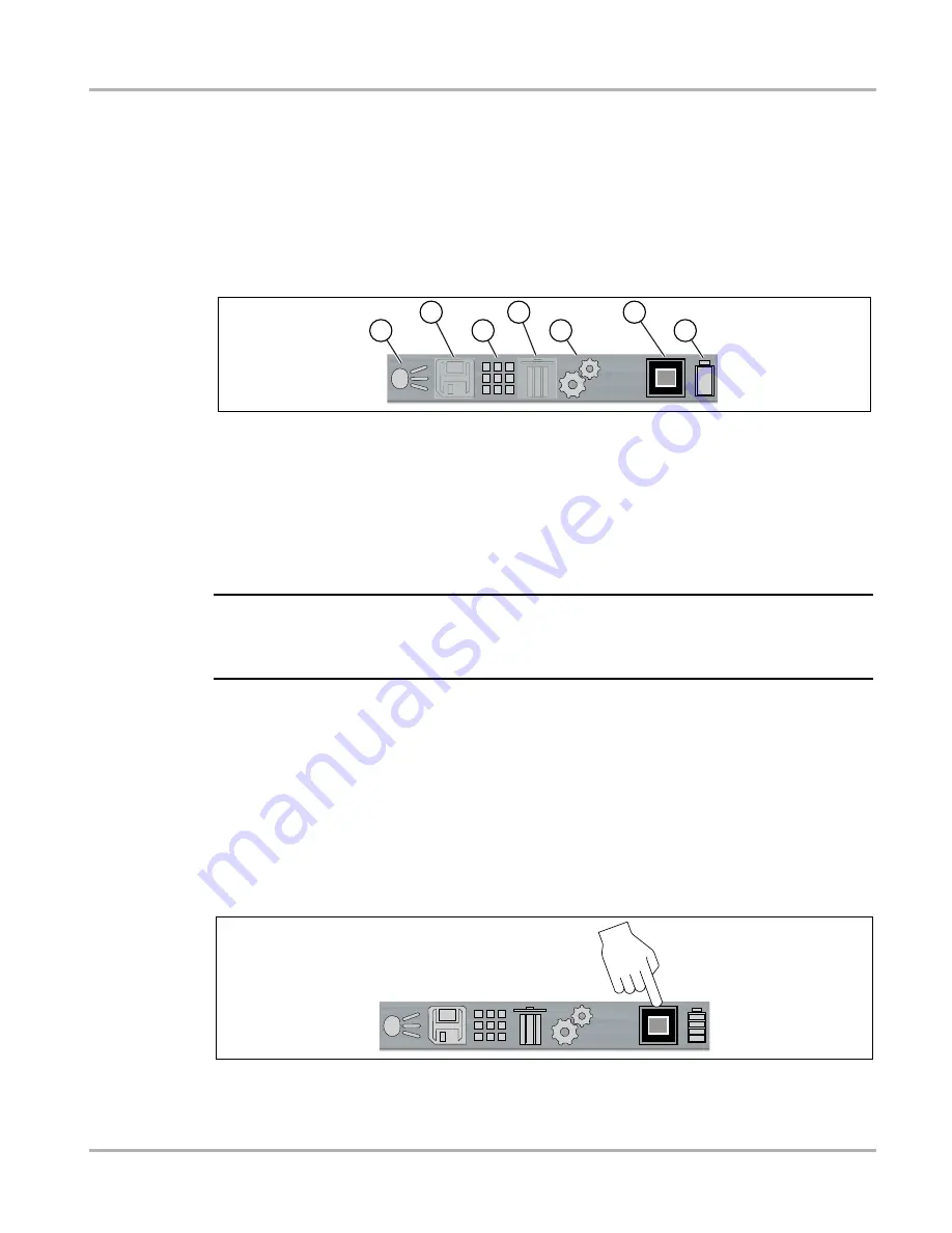
The toolbar located at the top of the screen includes menu icons and status indicators.

Use the 

LEFT

/ RIGHT

► control buttons to highlight an active icon from the toolbar, then press 

the 

Y

 button to select it.

Icons are feature dependent and are only active when applicable. As example in 

Figure 4-1

 the 

Save and Delete icons are inactive (grayed out). 

1.

LED Spotlight Indicator (on / off) 

2.

Save Icon (saves screen image)

3.

Gallery Icon (opens image gallery)

4.

Delete Icon


(deletes image)

5.

Settings Icon (opens Setting menu)


6.

View Indicator

7.

Battery Charging Level Indicator


Figure 4-1 

NOTE:

i

LEFT

, RIGHT

►, 

UP▲

, and 

DOWN▼

 control button functionally is the same for all menus. 

Highlight the item, then press 

Y

 to select it. Press the 

N

 button to return to the last screen or press 

it repeatably to return to the Thermal View.

4.4   Changing Viewing Modes

There are seven viewing modes:

Blended thermal opacity at 20, 40, 60, 80, 100%, and diffused beam

Laser Spot Temperature 

When using any of the blended thermal opacity modes, the Opacity Level icon in the toolbar 
indicates the current opacity level (

Figure 4-2

).

Figure 4-2 

1

2

3

4

5

6

7

Summary of Contents for Thermal Laser

Page 1: ...User Manual BC ...

Page 2: ... States and elsewhere visit https patents snapon com Disclaimer of Warranties and Limitation of Liabilities All pictures and illustrations shown are for reference purposes only All information specifications and illustrations in this manual are based on the latest information available at the time of printing and are subject to change without notice While the authors have taken due care in the pre...

Page 3: ...or in compliance with the guidelines and regulations set forth by the following United States and Canada Europe Australia California Only California Energy Commission CEC U S and Canada Underwriters Laboratories UL Conformité Européene European Conformity Regulatory Compliance Mark RCM ...

Page 4: ...gdom Website https www snapon com diagnostics uk Phone 44 0 845 6066512 E mail https www snapon com diagnostics uk Australia and New Zealand Website http www snapontools com au Phone Australia 1800 810 581 New Zealand 0800 762 766 E mail sota diagnostics snapon com The Netherlands and Belgium Website http www eurotechcenter nl Phone NL 31 0 356 242322 BE 32 0 380 80537 E mail helpdesk eurotechcent...

Page 5: ...ng Modes 6 Using Laser Spot Temperature Mode 8 Taking Thermal Temperature Readings 9 More About Temperature Readings 9 Saving and Managing Screenshots 10 Saving Screenshots 10 Viewing Screenshots 10 Deleting Screenshots 11 Transferring Screenshots to a PC 11 Using the LED Spotlight 13 Chapter 5 Settings 14 Main Topic Links 14 Settings Menu 14 Color Palette 15 Brightness 16 Language 16 Automatic Sh...

Page 6: ...vi Contents Battery Pack 22 Safety Guidelines 22 Battery Information 22 Battery Charging 22 Disposal 25 Chapter 7 Troubleshooting 26 General Troubleshooting Chart 26 ...

Page 7: ...ons and variations in the products that can be tested with this instrument we cannot possibly anticipate or provide advice or safety messages to cover every situation It is the responsibility of the automotive technician to be knowledgeable of the system being tested It is essential to use proper service methods and test procedures It is important to perform tests in an appropriate and acceptable ...

Page 8: ...erate or minor injury to the operator or to bystanders Safety Message Conventions Safety messages are provided to help prevent personal injury and equipment damage Safety messages communicate the hazard hazard avoidance and possible consequences using three different type styles Normal type states the hazard Bold type states how to avoid the hazard Italic type states the possible consequences of n...

Page 9: ... manual 1 1 Conventions 1 1 1 Bold Text Bold emphasis is used in procedures to highlight selectable items such as buttons and menu options Example Select LEFT RIGHT control buttons 1 1 2 Symbols The greater than arrow indicates an abbreviated set of selection instructions Example Select Settings Advanced Emissivity The above statement abbreviates the following procedure 1 Select the Settings icon ...

Page 10: ...t indicates a situation which if not avoided may result in damage to the test equipment or vehicle Example IMPORTANT Do not use any abrasive cleansers or automotive chemicals on the tool 1 1 5 Hyperlinks Hyperlinks or links that take you to other related articles procedures and illustrations are available in electronic documents Blue colored text indicates a selectable hyperlink Example IMPORTANT ...

Page 11: ...1 to 2 5 ft 30 48 to 76 2 cm Spot Size Ratio 10 1 LED Spotlight Low 7 lumens Med 12 lumens High 22 lumens Image Storage Memory Capacity 300 image files Image File Format jpg USB Interface 2 0 USB micro USB Battery Rechargeable Lithium Ion Battery Pack 3 7V 2150mAh nominal Approximate eight hour continuous operation with brightness level at 50 Approximate 80 charge in three hours 100 charge in less...

Page 12: ...iving you the ability to make accurate spot temperature measurements The Thermal Laser also has the capability to capture screenshots in all viewing modes 1 UP DOWN Buttons change thermal laser views 2 LEFT RIGHT Buttons navigate the toolbar 3 N X Button cancel selection 4 Power Button on off 5 micro USB Jack charge the battery and connect to PC 6 Laser pointer 7 Thermal Lens sensor 8 Camera Lens ...

Page 13: ... Laser is ready for use however to ensure optimal measurement accuracy it is recommended to allow the Thermal Laser to warm up a minimum of five minutes before operation After the Power button is pressed an audible tone is sounded upon startup Power Off To turn the Thermal Laser OFF press and hold the Power button for a minimum of two seconds until the Thermal Laser turns off NOTE i The active vie...

Page 14: ...pens image gallery 4 Delete Icon deletes image 5 Settings Icon opens Setting menu 6 View Indicator 7 Battery Charging Level Indicator Figure 4 1 NOTE i LEFT RIGHT UP and DOWN control button functionally is the same for all menus Highlight the item then press Y to select it Press the N button to return to the last screen or press it repeatably to return to the Thermal View 4 4 Changing Viewing Mode...

Page 15: ...o increase thermal opacity full UP 100 Figure 4 3 Press the DOWN control button repeatedly to decrease thermal opacity Figure 4 3 Figure 4 3 At the 20 level Figure 4 3 pressing DOWN once displays the Diffused Beam view This view displays at 100 opacity at center and gradually decreases radially to 0 Figure 4 4 Figure 4 4 From the Diffused Beam view pressing DOWN once displays laser spot temperatur...

Page 16: ...eatedly until Press TRIG to start measurement is displayed on the screen and the Laser icon displays in the toolbar Figure 4 2 NOTE i The X in the laser icon Figure 4 2 indicates the laser pointer is off When the trigger is pulled the laser pointer turns on and the X is not displayed in the icon Figure 4 5 2 To take a measurement pull and hold the trigger to activate the laser pointer 3 Point the ...

Page 17: ...reading onscreen To take temperature measurements using laser spot mode see Using Laser Spot Temperature Mode on page 8 4 6 1 More About Temperature Readings The Thermal Laser measures the emitted infrared radiation from an object s and then uses a known emissivity value to effectively calculate the temperature value displayed on the screen To accurately calculate temperature from infrared radiati...

Page 18: ...mperature values arrows Figure 4 2 of the scene It is normal for the min max temperature values to constantly change 4 7 Saving and Managing Screenshots 4 7 1 Saving Screenshots 1 Point the Thermal Laser at the object to be measured 2 Pull and release the trigger 3 Press the Y button to save the screenshot image Press the N button to continue without saving the screenshot 4 7 2 Viewing Screenshots...

Page 19: ...n capture trigger is pulled or the gallery icon is selected while the USB cable is connected to a PC an error message is displayed To resume saving screenshots disconnect the USB cable from the PC The Thermal Laser can be connected to a PC using the supplied USB cable This allows you to transfer saved screenshots to the PC 1 Open the protective cover on top of the Thermal Laser and connect the USB...

Page 20: ... saved screenshots from the USERDATA folder Figure 4 11 6 Select the files to copy move from the Thermal Laser to your PC 7 When finished if required perform any Windows procedures to Safely Remove Hardware or Eject Media to stop communication with the Thermal Laser 8 Disconnect the USB cable from the PC and the Thermal Laser 9 Close the protective cover ...

Page 21: ...vel see Spotlight Intensity on page 18 NOTE i When the battery reaches a low charge level approximately one bar indication on icon the LED spotlight is disabled The spotlight will be functional again when the battery has been charged to approximately 30 Always turn the spotlight off before and when charging the battery NOTE i The battery discharge rate will vary depending on overall use and settin...

Page 22: ...Use the LEFT RIGHT control buttons to highlight the Settings icon from the toolbar Figure 5 1 Press the Y button to select it Figure 5 1 2 Use the UP DOWN control buttons to select an option from the menu Figure 5 2 Press the Y button to select it NOTE i LEFT RIGHT UP and DOWN control button functionally is the same for all menus Highlight the item then press Y to select it Press the N button to r...

Page 23: ...ed to help define enhance object temperatures onscreen by varying color ranges contrast and brightness The Color Palette setting allows you to choose one of five color palette presets Figure 5 3 Figure 5 3 Color Palette Brightness Temperature Power Emissivity Iron Rainbow Plasma Cool Hot Grey Iron ...

Page 24: ...WN control buttons to change the brightness setting Each press incrementally changes the lighting level by 10 Figure 5 4 5 2 3 Language The Language setting allows you to select your preferred language Figure 5 5 Menu Options English French Spanish Italian Polish Dutch German Portuguese Figure 5 5 90 English Deutsch Español Français Italiano ...

Page 25: ...ips are provided for select menu navigation procedures to help you become familiar with the Thermal Laser menus Each Tip will appear only once after turning on the Thermal Laser The Navigation Tips setting allows you to turn on enable or turn off disable the automated navigational tips Figure 5 7 Figure 5 7 No Automatic Power Off Power Off After 2 Minutes Power Off After 5 Minutes Power Off After ...

Page 26: ...ttings are provided Low Eco 7 lumens Medium 12 lumens High 22 lumens default setting Figure 5 8 5 2 7 Advanced The following selections Temperature Emissivity Object Distance and About are available within the Advanced menu Temperature The Temperature setting allows you to set the temperature unit of measure F or C Figure 5 9 Figure 5 9 Low Eco Medium High F C ...

Page 27: ...missivity value is used to effectively calculate the displayed temperature value Emissivity is the amount of radiation emitted from an object compared to that of a perfect blackbody standard of radiation of the same temperature Emissivity can be effected by other factors listed below which is beyond the scope of this manual Core material makeup Surface condition Temperature Angle of view Wavelengt...

Page 28: ... the object the misalignment decreases Therefore to optimize the accuracy of the Thermal Laser when used in close proximity of an object 1 to 3 feet 30 48 to 91 44 cm the Object Distance setting should be set to Near About Factory Reset Selecting About displays hardware and software version information and provides the option to reset the device to factory settings Select Ok to exit the screen Sel...

Page 29: ...lay and controls for dirt and damage before and after each use Clean the Thermal Laser housing and display screen with a damp soft cloth and a weak detergent cleaner IMPORTANT Do not use paper towel or other paper type materials to clean the display screen Do not use any abrasive cleansers or automotive chemicals IMPORTANT Only use cleaning solution specified for cleaning commercial digital camera...

Page 30: ... period of time about 30 days after charging to prevent loss of capacity due to self discharging If the battery pack no longer holds a charge contact your sales representative 6 4 3 Battery Charging There are three modes of charging Low Rate approximate charge rate 100mA Thermal Laser turned on USB cable connected to a powered PC USB jack Medium Rate approximate charge rate 500mA Thermal Laser tur...

Page 31: ...able to the micro USB jack Figure 6 1 IMPORTANT It is highly recommended to use the supplied USB power supply adapter to charge the battery Using a non approved power supply adapter max 500mA charge rate output may result in insufficient charging 4 Connect the USB cable to the USB power supply adapter 5 Connect the USB power supply adapter to a live AC power source NOTE NOTE i The battery pack wil...

Page 32: ... When the battery charge level drops to approximately 10 minutes of power left the icon will flash on off as a reminder to connect the USB power supply adapter If the charger is not connected the unit will continue operate until it automatically turns off due to low power A warning message will be displayed before shutdown Low Battery The unit will power down in 30 seconds please connect to a char...

Page 33: ...wing markets contact North America Rechargeable Battery Recycling Corporation RBRC at http www rbrc org or http www call2recycle org or call 1 800 822 8837 USA United Kingdom Electrical Waste Recycling Company at http www electricalwaste com Australia Australian Battery Recycling Initiative http www batteryrecycling org au New Zealand Ministry for the Environment https www mfe govt nz issues waste...

Page 34: ...correct Change the emissivity setting b Condensation or debris on thermal and or camera lenses Clean lenses or place imager in a dry area at room temperature until condensation clears Temperature measurement display is non responsive a If the symbol displays in front of the Center Region Temperature Average value this indicates the maximum measurable temperature has been reached e g 1000 F 538 C b...

Reviews: