background image

7

ASSEMBLING THE UNIT

Position the welding machine so as to allow the free circulation 
of air inside and, as much as possible, prevent metal or other 
dusts from penetrating.
•  The machine must be installed by professional personnel.
•  All  the  connections  must  be  performed  in  compliance 

with applicable standards (IEC/CEI EN 60974-9) and with 
accident-prevention laws.

•  Make sure the power supply voltage corresponds to the 

welding machine rating. 

•  The protection fuses must be sized according to the details 

shown on the technical data plate.

Make  sure  the  ground  wire 

D

,  inside  the  reel 

compartment,  is  connected  to  the  negative  pole 
coming out of the dividing wall. 
The polarity is stamped alongside the two terminals, the 
polarity is stamped on. The positive pole + is that at the 
top, nearest to the wire feed motor. The negative pole – is 
the one lower down, nearest to the ground lead exit.

Connect the ground lead clamp 

D

 to the piece to be welded. 

Open  the  side  door.  Install  the  wire  reel  according  to  the 
instructions provided below.

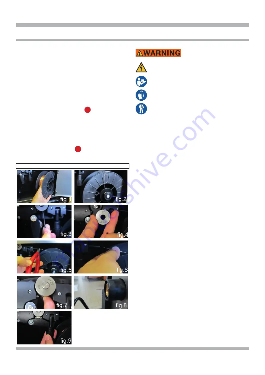
REEL FITTING SEQUENCE

Electrical shock can result when contacting live 
electrode or internal components 
Electrical  shock  can  result  from  absence  of 
grounding lug. 

Welding  machine  must  be  connected  to 
power source in accordance with applicable 
electrical codes. 
Please refer to the troubleshooting tip section 
located at our web site (www.800ABCWELD.
com) for information on wiring the 220 V plug 
if needed.
Do  not  touch  electrode  or  internal  compo-
nents without protection. 
Disconnect power before servicing. 
Do not remove the grounding lug in any elec-
trical plug.


Electrical shock can cause injury.


During  wire  installation,  the  welder  must  be  switched 
off and unplugged to prevent the moving motor roller to 
move presenting a risk for the operator.

•  Install the reel on the support inside the compartment 

as shown in fig. 1.

•  The  reel  must  be  installed  on  the  support  so  the 

wire  unwinds  in  an  counter-clockwise  direction.  It  is 
important for the wire to be stopped on the reel on the 

side  closest  to  you,  see  fig.  2.  Install  the  reel  on  the 

support, as shown in the illustration.

•  Make  sure  the  drive  roller  is  correctly  positioned 

according  to  the  diameter  and  type  of  wire  used.  To 

remove the roller, align the flat part of the roller-bearing 
pin at the bottom, so the key can be fitted inside the 

retention  screw.  Loosen  the  screw,  remove  the  roller, 
install the roller back on so the race corresponds to the 

wire used, see figures 3 and 4.

•  Cut  the  wire  with  a  Snap-on  cutting  pliers  87ACF  or 

equivalent,  keeping  it  between  your  fingers  so  that  it 

cannot unwind, insert it inside the plastic tube exiting 

from the gear motor and, with the aid of a finger, also 

insert it inside the steel tube until it comes out of the 

brass adapter, see figures 5-6-7-8.

•  Close  the  drive  arm,  being  careful  of  the  wire,  which 

must be aligned with the roller race, see fig. 9.

•  Install the welding torch.
After installing the reel and torch, switch on the machine, 
select  the  suitable  synergic  curve,  following  the 
instructions  given  in  the  service  functions  (

PROCESS 

PARAMS

)  paragraph.  Remove  the  gas  nozzle  and 

unscrew the current nozzle of the torch. Press the torch 
button until the wire comes out. 

Summary of Contents for MIG160i

Page 1: ...al repairs to specific material types used in the body shop industry Welds a variety of material types and thicknesses such as steel stainless steel aluminum high strength and boron steels Preset synergic curves automatically provide proper settings for individual situations and reduce set up times INTRODUCTION form WC 6000 3 300 048 B INSTRUCTION MANUAL FOR WIRE WELDING MACHINE ...

Page 2: ...e of Contents 2 Safety Information 3 4 Specifications 5 Features 6 Description of Equipment 6 Assembling the Unit 7 9 Quick start guide 9 11 Advanced setting 11 12 Maintenance 13 Replacement Parts 14 15 Wiring Diagram 16 Warranty Service and Repair 17 ...

Page 3: ...icon when present gives a graphical description of the potential hazard Arc Welding Electric welding or plasma cutting causes ultra violet rays and weld spatter Bystanders will be exposed to ultraviolet rays and weld spatter Wear welding helmet with appropriate shade lens while using electric welders or plasma cutters Do not allow bystanders while welding or cutting Wear safety shield and protecti...

Page 4: ...de torch lead around your body Do not work next to welding cutting power source Electrical shock and Magnetic fields can cause injury Disposal of Equipment IMPORTANT Disposal of electrical equipment can be hazard ous to the environment Contact local regulations prior to disposal Improper disposal can cause an environmental hazard FUMES AND GASES can be dangerous to your health ITEMS REQUIRED FOR M...

Page 5: ...yed type to be used as a protection for the equipment IP23S Protection rating for the housing Grade 3 as the second digit means that this machine may be stored but it is not suitable for use outdoors in the rain unless it is protected S Suitable for use in high risk environments NOTE The equipment has also been designed for use in environ ments with a pollution rating of 3 See IEC 60664 SPECIFICAT...

Page 6: ...re speed for multiple material thicknesses MIG welding of steel stainless steel and MIG brazing of high strength and Boron steels Welds 5356 and 4047 aluminum with optional torch kit Spot weld and pause features with adjustable on time Adjustable arc length inductance burnback and soft arc starting Faster set up time and reduced production times Over 30 years of industry leading technical support ...

Page 7: ...Disconnect power before servicing Do not remove the grounding lug in any elec trical plug Electrical shock can cause injury During wire installation the welder must be switched off and unplugged to prevent the moving motor roller to move presenting a risk for the operator Install the reel on the support inside the compartment as shown in fig 1 The reel must be installed on the support so the wire ...

Page 8: ...uitable for the aluminum wire you have to weld Install the torch prepared for aluminum PREPARING THE STEEL TORCH FOR WELDING ALUMINUM USING OPTIONAL ALUMINUM KIT MIG 160AK AND OPTIONAL ROLLER CKS 3080942 Remove the metal liner located inside the wel ding torch see figure Insert the carbon teflon liner see figure On the liner protruding from the torch insert the brass mandrel the O ring and the loc...

Page 9: ...ain applications is therefore the car body repair but it can also be used for repairing other galvanized structures within the maximum thickness QUICK START GUIDE 1 TURN ON THE WELDER USING THE ON OFF SWITCH When the machine is switched on for a few moments the display screen A displays the model number of the machine the version and development date of the software and the release number of the s...

Page 10: ...from thin sheet to strutural Fe 035 Steel 100 CO2 023 to 200 All purpose steel welding from thin sheet to strutural Fe 040 Steel 75 Argon 25 CO2 023 to 200 All purpose steel welding from thin sheet to strutural Fe 040 Steel 100 CO2 023 to 200 All purpose steel welding from thin sheet to strutural 308L 030 Stainless Steel 98 Argon 2 CO2 030 to 137 301 302 304 and 305 Stainless Steels 308L 035 Stain...

Page 11: ...ED SETTING Welding Mode Selecting mode 2T the machine starts welding when the torch button is pressed and stops when this is released Selecting mode 4T to start welding press and release the torch button To stop welding press and release again To choose the welding start mode 2T or 4T select one of the 2 modes by means of the knob B and press the knob B for less than 2 seconds to confirm the choic...

Page 12: ...access this function simply highlight it using the knob B and press it for less than 2 seconds The display screen A shows the adjustment bar The figure can be changed and confirmed by pressing the knob B for less than 2 seconds LCD Contrast The adjustment may range from 0 to 100 This function can be used to increase or decrease the brightness of display screen A To access this function simply high...

Page 13: ...make sure the switch F is in O position and that the power supply cable is disconnected from the mains Periodically also clean the inside of the appliance and remove any metal dust using compressed air HOW TO PROCEED AFTER MAKING REPAIRS After making repairs always ensure the wires are fully insulated between the primary side and the secondary side of the machine Avoid the wires coming into contac...

Page 14: ...14 REPLACEMENT PARTS PARTS LIST ...

Page 15: ...M16021 INSIDE BAFFLE 22 CKSM16022 SPACER COIL SUPPORT 23 CKSM16022 SPRING 24 CKSM16022 RING 25 CKSB7116370 FITTING OUTLET 26 CKSM16026 SOLENOID VALVE 27 CKSB7107370 FITTING BARB INLET 28 CKSM16028 BACK PANEL 29 CKSP3010 COVER SWITCH 30 CKSB7129370 SWITCH 31 CKS251069 POWER CORD 32 CKSM16032 MOTOR WITH FAN 33 CKSM16033 SUPPORT 34 CKSM16034 POWER CIRCUIT 35 CKSM16035 COVER 36 CKSM16036 FIXED SIDE PA...

Page 16: ...16 WIRING DIAGRAM ...

Page 17: ...ent of the Equipment by other than Seller s authorized representatives e installation repair or maintenance other than specified operator maintenance of the Equipment or related equipment attachments peripherals or optional features by other than Seller s authorized re presentatives D improper or negligent use application operation care cleaning storage or handling E fire water wind lightning or o...

Page 18: ...torch The liner sJck out should just stop just short of the drive roller 6 Install the enclosed aluminum 035 wire and feed it into the guide tube and then into the torch liner 7 Close the drive arm and be careful that the aluminum wire is aligned in the roller grove Very Important Do not over increase the wire roller tension with the tension knob This will cause the wire to bird nest between the r...

Reviews: