background image

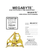
MEGABYTE™

                      TABLE OF CONTENTS

Smoracy, LLC

PRINTED 2/01

PAGE 1

TABLE OF CONTENTS

NOTE- ANY PART, PORTION, DESIGN, NUMBER, SPECIFICATION, AND/OR

DIMENSION IN THIS MANUAL IS SUBJECT TO CHANGE WITHOUT
NOTICE BY THE MANUFACTURER.

                   PAGES

INTRODUCTION & WARRANTY ...................................................2
SAFETY PROCEDURES ............................................................... 7
SAFETY DECALS ......................................................................... 9
OPERATING PROCEDURES ...................................................... 12
INSTALLATION PROCEDURES ................................................. 13
LUBRICATION ............................................................................. 19
MAINTENANCE ........................................................................... 20
HYDRAULIC SECTION ............................................................... 22
REPLACEMENT PARTS SECTION ............................................ 23

Summary of Contents for MEGABYTE

Page 1: ..._______ Phone No _________________ Delivery Date ______________ MEGABYTE ATTENTION Depending on what replacement parts you are ordering we will need the following information SERIAL NUMBER OF MEGABYTE EXCAVATOR MAKE AND MODEL MANUFACTURED BY SMORACY LLC 6750 Millbrook Road REMUS MICHIGAN 49340 PHONE 517 561 2270 OR 561 2272 FAX 517 561 2273 SALES DEPT FAX 517 561 2962 PARTS SERVICE MEGABYTE PRINTE...

Page 2: ......

Page 3: ... NUMBER SPECIFICATION AND OR DIMENSION IN THIS MANUAL IS SUBJECT TO CHANGE WITHOUT NOTICE BY THE MANUFACTURER PAGES INTRODUCTION WARRANTY 2 SAFETY PROCEDURES 7 SAFETY DECALS 9 OPERATING PROCEDURES 12 INSTALLATION PROCEDURES 13 LUBRICATION 19 MAINTENANCE 20 HYDRAULIC SECTION 22 REPLACEMENT PARTS SECTION 23 ...

Page 4: ...ury Personnel using the Megabyte must be qualified trained and familiar with the operating procedures as defined in this manual WARNING It is the responsibility of the owner or employer to insure that the operator is trained and practices safe operation while using and servicing the equipment It is also the owner s responsibility to provide and follow a regularly scheduled preventative maintenance...

Page 5: ......

Page 6: ...MEGABYTE SERVICE RECORD SERVICE RECORD DATE DESCRIPTION AMOUNT Smoracy LLC PRINTED 2 01 PAGE 6 ...

Page 7: ...rmally happens after the person has become accustomed to the machinery In the initial start up and operation of the machinery they are cautious they are very careful because they do not understand the machine Never split any materials that might contain wires stones nails or other metal objects which may damage the blades and become dangerous projectiles WARNING Most of the nuts used on the Megaby...

Page 8: ...the equipment DANGER DO NOT GO NEAR HYDRAULIC LEAKS High pressure oil easily punctures skin causing serious injury gangrene or death DO NOT use fingers or skin to check for leaks Lower load or relieve hydraulic pressure before loosening fittings WARNING DANGER WARNING Operators must at all times be located within easy reach of all feed control and shut off devices when the unit is running DANGER N...

Page 9: ...C before applying decal 3 When the need arises to replace a machine component with a decal attached be sure and replace the decal 4 Replacement decals are available and can be purchased from the manufacturer or your Smoracy LLC Dealer 5 Spanish Portuguese and other foreign language decals are available EXAMPLES Smoracy LLC PRINTED 2 01 PAGE 9 GREASE DAILY KEEP HANDS CLEAR THIS MACHINE IS CONVERED ...

Page 10: ... DECAL LOCATIONS MEGABYTE ALTHOUGH LOCATIONS MAY VARY ALL DECALS MUST BE ON EQUIPMENT DURING OPERATION IF ANY DECALS BECOME DAMAGED REPLACE IMMEDIATELY Smoracy LLC PRINTED 2 01 PAGE 10 2 5 1 6 8 5 7 3 4 2 5 2 5 3 4 8 6 1 7 2 ...

Page 11: ...ler or manufacturer for most current decal package LOCATION NUMBER DESCRIPTION 1 OOB 150 Smoracy LLC 2 OOB 275 Grease Daily 3 OOB 287 Notice Patent Pending 4 OOB 2003 Notice The Owner Is 5 OBR 400 Danger Keep Hands Clear 6 OBR 436 Danger Flying Objects 7 OBR 4031 Warning Do Not Go Near 8 Megabyte Vinyl Smoracy LLC PRINTED 2 01 PAGE 11 ...

Page 12: ...ur shut down the equipment and recheck all nuts and bolts It is normal for bolts to loosen once on a new piece of machinery If you tighten system idle for approximately 15 minutes to allow the system to warm up to operating temperature This equipment is intended for use by personnel who are experienced with similar equipment Always operate equipment safely It is also recommended that someone else ...

Page 13: ...low these instructions DANGER Step 1 Detaching Bucket and Setting Up Megabyte Step 2 Positioning Excavator Stick Step 3 Pin Installation Step 4 Saddle Clamp Installation Step 5 Attaching Megabyte Link Excavator Link and Excavator Hydraulic Cylinder Step 6 Auxiliary Hydraulic Installation NOTICE Auxiliary valve hookup is required if your excavator does not have this accessory see the excavator manu...

Page 14: ...ne on bucket and to stick 4 Remove pin holding bucket to end of stick Leaving upper links attached to stick 5 Remove bucket 6 Start machine and raise stick high enough to fit the Megabyte on its stand under stick 7 Position Megabyte in place 8 Remove saddle clamps and lay the Megabyte link back FIGURE 1 SADDLE CLAMP MEGABYTE LINK ADAPTOR AND PIN SADDLE LOCATOR SADDLE CLAMP SADDLE CLAMP ...

Page 15: ... the pin hole on the bottom of the excavator is centered with the pin holes on the saddle locators Make sure that the excavator stick is centered on the Megabyte base plate 2 Remove the original dogbone from the excavator stick by removing the pin connecting the dogbone to the excavator cylinder Do not reinstall pin at this time FIGURE 2 EXCAVATOR STICK ORIGINAL DOGBONE SADDLE LOCATOR CENTER UP HO...

Page 16: ... excavator stick and both saddle locators Make sure the saddle locators are in the correct position before beginning to weld 5 Use E 7018 stick electrodes to weld saddle locators in place to the base plate with full perimeter welds YOU MUST USE FULL PERIMETER WELDS TOP BOTTOM RIGHT AND LEFT SIDE NOTE Mig process may be used using an equivalent E 70 series type wire See Darkened areas of Figure 3 N...

Page 17: ... and tapered washers provided See Figure 5 5 Adjust clamps to fasten down as tight as possible against excavator stick Once clamps are adjusted cut off any excess metal from the top of the saddle clamp arms 6 Tighten down clamps to eliminate any movement front to back and side to side of excavator stick 7 Torque bolts to 700 ft lbs 8 The kit includes three different width cross members use the siz...

Page 18: ...pin through cylinder eye and into second Megabyte Link bushing 5 Swing second excavator link up in line with pin and push pin through 6 Lock pin in place with bolt on bushing provided with pin FIGURE 6 EXCAVATOR CYLINDER PIN LOCATION EXCAVATOR LINK MEGABYTE LINK EXCAVATOR STICK STEP 6 AUXILIARY HYDRAULIC INSTALLATION 1 Auxiliary hydraulic valve set up should already be installed Per Manufacturers ...

Page 19: ...5 X Anvil Link Bushing Smoracy LLC PRINTED 2 01 PAGE 19 EXCAVATOR Follow original equipment manufacturers requirements for proper lubrication procedures CLYINDER REAR PIVOT BUSHING Grease this bushing daily CLYINDER CLEVIS PIN Grease this pin daily KNIFE PIVOT BUSHING Grease this bushing daily ANVIL PIVOT BUSHING Grease this bushing daily ANVIL LINK BUSHING Grease this bushing daily 1 2 4 3 5 ...

Page 20: ...set to correct P S I O K Repaired ITEMS TO BE SERVICED DAY WEEK MONTH PROCEDURE Always Replace If Needed CHECK Check Entire Machine X For any loose parts or components Hydraulic Oil Leaks Hoses Fittings X Inspect tighten repair or replace Safety Decals X Replace immediately if damaged Check Blade Bolts and Nuts X SEE BOLT TORQUE CHART Check Wear On Teeth X If worn out replace Check Wear On Wedge X...

Page 21: ...hydraulic oil leaks Check all hoses fittings lines repair or replace 3 Check the safety decals replace if missing or damaged 4 Check cutting blade assembly Inspect cutting blade torque bolts and nuts properly 5 Check Teeth Inspect teeth for wear Replace if worn out 6 Check Wedge Check wedge for wear Replace if worn out MONTHLY MAINTENANCE 1 Check all hydraulic pressures Reset all to correct P S I ...

Page 22: ... mounted on the excavator Maximum cylinder force is controlled by the excavator relief valve setting Smoracy LLC PRINTED 2 01 PAGE 22 Control Valve Relief Valve Filter Strainer Hydraulic Pump Tank Excavator Hydraulics 6 Bore X 45 Stroke Cylinder Supplied On Megabte 900 3917 54 MEGABYTE HYDRAULIC FLOW CHART T i m e S e c o n d s THE MEGABYTE HYDRAULIC SYSTEM MEGABYTE HYDRAULIC SCHEMATIC 5 10 15 20 ...

Page 23: ...nt parts you are ordering we will need the following information SERIAL NUMBER OF MEGABYTE EXCAVATOR MAKE AND MODEL Smoracy LLC reserves the right to make changes in models size design installations and applications on any part without notification Smoracy LLC PRINTED 2 01 PAGE 23 ...

Page 24: ...MEGABYTE REPLACEMENT PARTS Smoracy LLC PRINTED 2 01 PAGE 24 18 FOR EQUIPMENT BUILT BEFORE S N 1016 ...

Page 25: ... 0000 33 Blade Cylinder Base Pin 9 969 0500 23 Complete Stick Frame 10 900 9902 41 Split Bearing Bushing 11 900 9902 27 Split Bushing 12 900 0501 01 Complete Blade Assembly 13 969 0001 09 Lower Blade Cutting Edge 14 969 0001 08 Middle Blade Cutting Edge 15 969 0001 07 Upper Blade Cutting Edge 16 969 0000 16 Blade Cylinder Pin 17 969 0000 25 Blade Pivot Pin 18 969 0510 00 Stand Assembly NOTE Nuts b...

Page 26: ...MEGABYTE REPLACEMENT PARTS Smoracy LLC PRINTED 2 01 PAGE 26 FOR EQUIPMENT BUILT S N 1016 AND AFTER 25 ...

Page 27: ...969 0000 27 Retaining Bushing 13 900 4905 12 Pivot Pin Bolt 5 8 11NC X 4 1 2 14 969 0000 10 Cylinder Base Pin 15 969 0004 51 Split Bearing Bushing 16 969 0000 25 Blade Pivot Pin 17 969 0004 50 Split Bearing Bushing 18 900 0501 01 Complete Blade Assembly 19 969 0001 09 Lower Blade Cutting Edge 20 969 0001 08 Middle Blade Cutting Edge 21 969 0001 07 Upper Blade Cutting Edge 22 969 0000 16 Blade Cyli...

Page 28: ...MEGABYTE REPLACEMENT PARTS Smoracy LLC PRINTED 2 01 PAGE 28 ...

Page 29: ... 969 0008 19 Tapered Washer 8 969 0008 18 Washer Kit 9 969 0008 20 Clamp Support 10 900 4900 79 Flat Washer 11 900 4904 53 Bolt 12 969 0008 Clamp See Note At Bottom 13 969 0008 09 Saddle Clamp Washer 14 Pin From Excavator NOTE When ordering saddle clamps saddle clamp components and saddle locators supply excavator make model number and S N of Megabyte NOTE Nuts bolts washers and all other componen...

Reviews: