


Figure 15.2 Slide the B and C gear shaft until the C gear meshes with the D gear
8.
Place the selected A gear, flange side in, on the A gear shaft and replace the C clip.
9.
Swing the bracket assembly until the A and B gears mesh. Hold the bracket assembly
in place and tighten the bolt. Make sure the gears turn smoothly before engaging the
powerfeed. You may need to make some adjustments.
10.
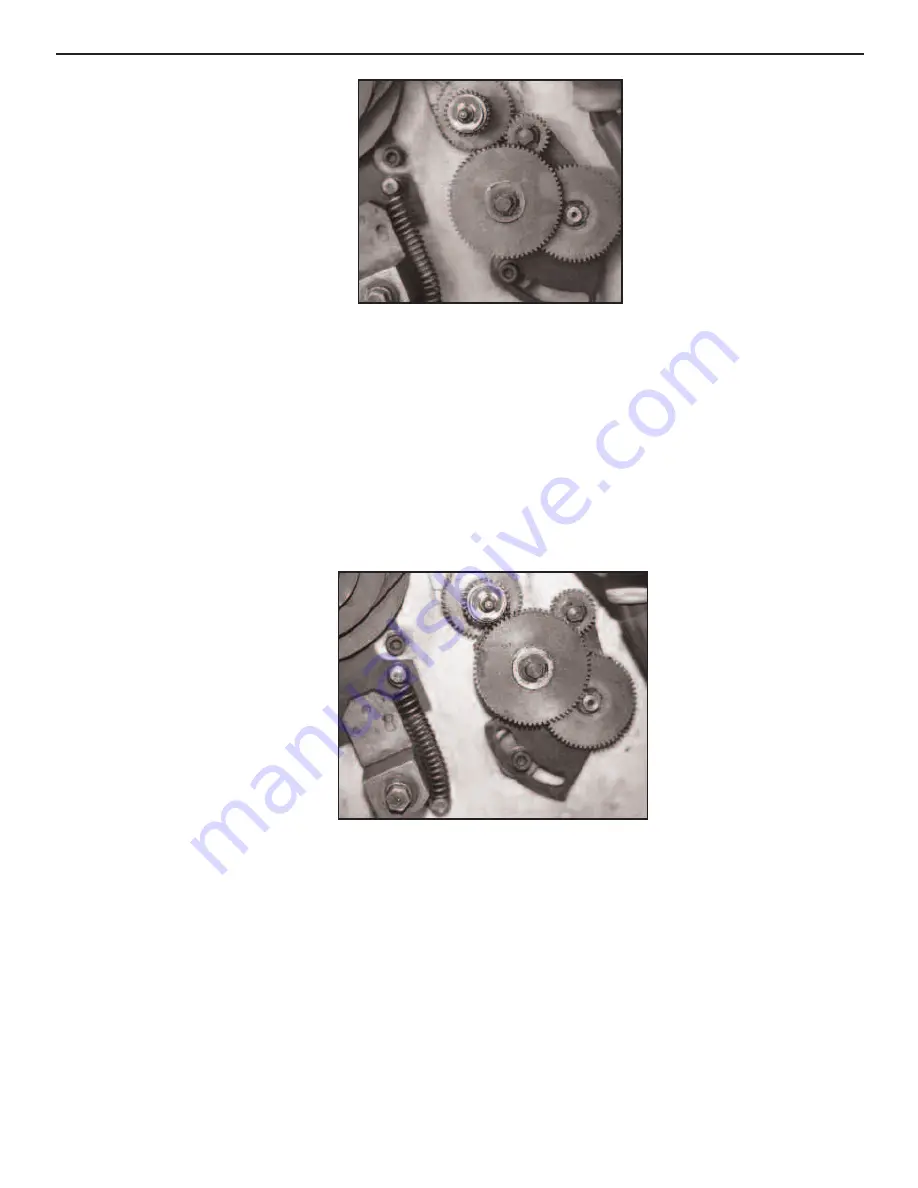
Engage the E gear between the C and D gears to reverse the leadscrew.
Figure 15.3 Engage the E gear between the C and D gears to reverse the leadscrew.
15: Changing Gears on your MI-1220 LTD
15-2
Or Visit www.smithy.com
Summary of Contents for MIDAS MI-1220 LTD
Page 102: ......
Page 103: ......
Page 104: ......
Page 105: ......
Page 106: ......
Page 107: ......
Page 108: ......
Page 109: ......
Page 110: ......
Page 111: ......
Page 112: ......
Page 113: ......
Page 114: ......
Page 115: ......
Page 116: ......
Page 117: ......
Page 121: ......
Page 122: ......
Page 123: ......
Page 124: ......
Page 125: ......
Page 126: ......
Page 127: ......
Page 128: ......
Page 129: ......
Page 130: ......
Page 131: ......
Page 132: ......
Page 133: ......