background image

25

Operation

PARTS MANUALS AVAILABLE ONLINE AT smithco.com

TROUBLE SHOOTING  NOZZLE VALVES

Plugged nozzle valves can be classified in two categories:

Plunger blockage.

Plunger stuck.

Plunger blockage results when larger debris catches between the orifice and plunger seal. This is the smallest
flow passage within the nozzle valve.

Stuck plungers result when smaller debris collects around the barrel of the plunger and binds the plunger in
place.

Symptoms of a blocked or stuck plunger are:

Constant spray.

Dripping when nozzle is shut off.

Pinched or split o-rings will also cause nozzles to drip.

 Operating a plugged nozzle valve for extended periods may result in nozzle valve coil
failure. Clean plugged nozzle valves immediately.

 If plugged nozzles are a frequent problem in a particular boom section, inspect the
machines boom filter screens for plugged or damaged screens. An 80 mesh screen
is recommended to prevent nozzles from plugging. Check the mesh size of the
strainers and replace if they are too coarse.

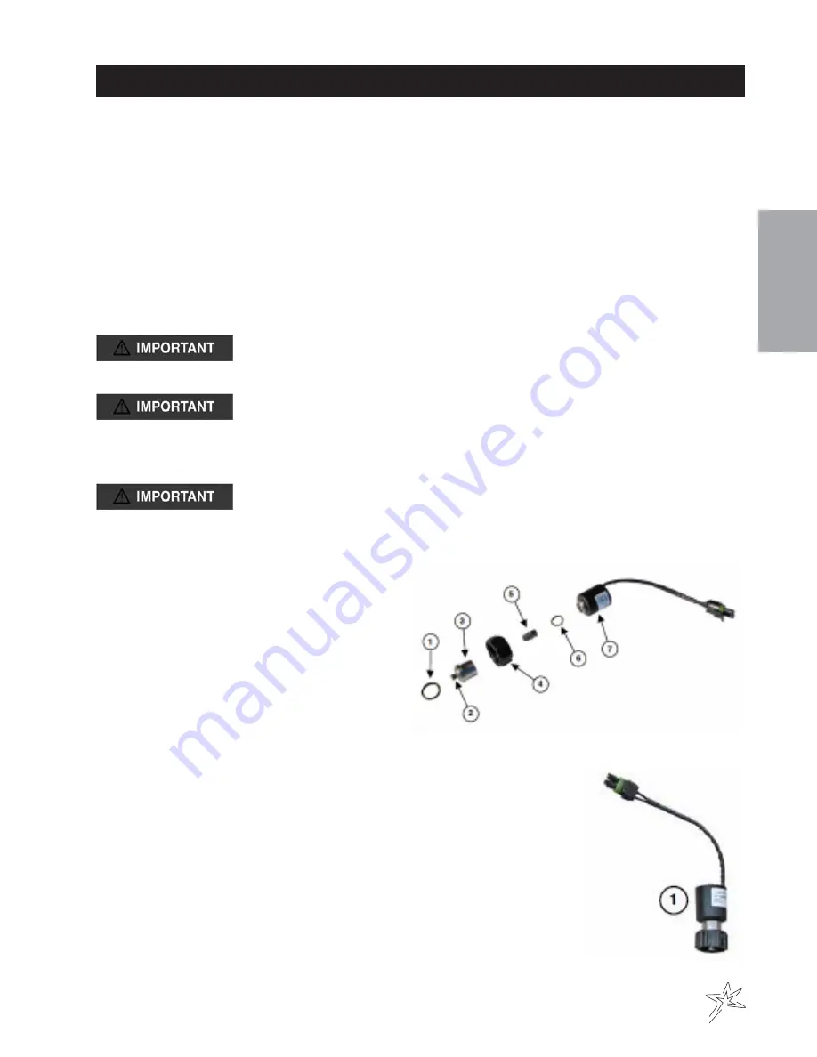
Nozzle valve component identification.

1.

O-ring

30-168-18P

2.

O-ring

30-168-20P

3.

Valve Body

30-168-26P

4.

Flynut

30-168-25P

5.

Plunger

30-168-17P

6.

O-ring

30-168-19P

7.

Coil

              30-168-21P

The nozzle valve assembly (30-168-05P) screws into the nozzle bodies replacing
the standard diaphragm check valve.

1.

Complete Nozzle Valve Assembly

30-168-05P

Summary of Contents for Spray Star 3185

Page 1: ...Spray Star 3185 3186 SharpShooter Rate Sync w Envizo Pro II for 18 and 20 Booms July 2016 Operator s Product Support Hwy SS Poplar Ave Cameron WI 54822 1 800 891 9435 productsupport smithco com ...

Page 2: ...nts 10 11 Operation 12 26 Operating Instructions 12 14 Envizio Pro II Do s and Don ts 14 SharpShooter Rate Sync Console Features 15 Initial Set Up of Envizio Pro II 16 19 SharpShooter Rate Sync Control 20 21 Spray Operation 22 Spray Introduction 23 Re Calibration of Flow Meter 23 Turf Management 24 Hose Handgun Spraying 24 Nozzle Troubleshooting 25 26 Reference 27 32 Collection Times 27 Blended Pu...

Page 3: ...s The serial number plate on the Spray Star 3180 is located on top of the frame between the hydro pump and spray tank Refer to engine manual for placement of engine serial number Refer to engine manual for place ment of engine serial number For product and accessory information help finding a dealer or to register your procuct please contact us at www Smithco com Information needed when ordering r...

Page 4: ...Release Hydraulic Oil Level Choke Open Choke Closed Hand Throttle Hour Meter Hour Meter Fuse Glow Plug Glow Plug Off Glow Plug On RPM Gasoline Diesel Water Temperature Temperature Light Engine Oil Engine Stop Engine Start Engine Run No Electrical Power Electrical Power Read Operator s Manual ...

Page 5: ...MBOLS No Smoking Moving Parts Manual Operation Pinch Point Step Hot Surface Hydraulic Fluid Penetration Lift Arm Tractor Engage Disengage PTO Ground Speed Fast Slow H High L Low F Forward R Reverse N Neutral Warning Danger Caution Up Raise Down Lower Up DownArrow ...

Page 6: ...hazardous situa tion that if not avoided will result in death or serious injury This signal word is to be limited to the most extreme situations typically for machine components which for functional purposes cannot be guarded WARNING Orange Indicates a potentially hazardous situation that if not avoided could result in death or serious injury and includes hazards that are exposed when guards are r...

Page 7: ...ied New decals are available from your authorized distributor This is a list of decals located on the Spray Star 3180 Part number description and location will help in reorder ing a decals A 15 463 Decal Spray Pump 25 375 Decal 94 dBA B 25 277 Decal Battery Warning C 25 286 Decal Pinch Point D 25 298 Decal Warning Hot E 25 321 Decal Diesel Fuel Only F 20 545 Decal Dash Panel G 30 157 Decal Control...

Page 8: ... 11 Disengage all drives and set park brake before starting the engine 12 Never use your hands to search for oil leaks Hydraulic fluid under pressure can penetrate the skin and cause serious injury 13 This machine demands your attention To prevent loss of control or tipping of the vehicle A Use extra caution in backing up the vehicle Ensure area is clear B Do not stop or start suddenly on any slop...

Page 9: ... replace immediately 12 Use only pipe hose and fittings rated for maximum pressure or pressure at which pressure relief valve is set at When replacing pipe hose or fittings use new product 13 Do not operate an engine in an enclosed area Be sure the area is well ventilated 14 Do not use these pumps for pumping water or other liquids for human or animal consumption 15 Do not pump flammable or explos...

Page 10: ...ont Two 20 x 11 00 x 10 Turf 20 psi 1 4 bar Rear Two 29 x 14 00 x 15 Multi Trac 30 psi 2 0 bar SPEED Infinitely Variable 0 10 m p h 0 18 kph BATTERY Automotive type 24F 12 volt BCI Group Size 24 Cold Cranking Amps 900 minimum Ground Terminal Polarity Negative Maximum Length 10 25 26 cm Maximum Width 6 88 17 cm Maximum Height 10 25 cm FLUIDCAPACITY Crankcase Oil See Engine Manual Fuel 7 gallon 26 5...

Page 11: ...om and any other Optional Equipment to the Prime Mover in accordance with instructions in the Spray Star 3180 Parts Service Manual The nozzles must be the correct distance above the turf as described in Turf Spraying Guide The spray boom must operate properly and the outer sections must break away safely if an object is struck by them they must then return to normal operation position 7 Be sure to...

Page 12: ...off by pushing on the bottom I Ground Speed Cruise Control This rocker switch initiates cruise control by pushing on the top and turning it off by pushing on the bottom Works with ground Speed Control Foot switch J Buzzer The buzzer sounds if the pump is running dry K Spray Pump This rocker switch turns the spray pump on by pushing on the top and off by pushing on the bottom L Left Boom Switch Thi...

Page 13: ...on pedal before disengaging speed control TOWING When it is necessary to move the Spray Star 3180 without the engine running there are 2 things that need to be done First the bypass valve built into hydrostatic pump must be open by turning it 1 4 turn to open The valve is located on the back side of the pump An open valve allows fluid to pass through the wheels freely When normal driven operation ...

Page 14: ...ews etc and tighten or replace as needed 5 Inspect hydraulic lines for damage or leaks Never use hands to inspect for leaks 6 Check the hydraulic fluid level The hydraulic fluid tank is located under the seat The fluid level should be 2 2 5 6 4 cm from the top of the tank when cold Use only SAE 10W 40 API Service SJ or higher Motor Oil 7 Inspect the steering throttle and shift linkages for good ho...

Page 15: ... Charge battery at 15 amps for 10 minutes or 7 amps for 30 minutes Do not exceed the recommended charging rate If electrolyte starts boiling over decrease charging Always remove grounded battery clamp first and replace it last Avoid hazards by 1 Filling batteries in well ventilated areas 2 Wear eye protection and rubber gloves 3 Avoid breathing fumes when electrolyte is added 4 Avoid spilling or d...

Page 16: ...7 6 28 8 5 32 4 2 15 9 50 3 4 12 2 46 2 5 32 5 5 20 8 100 6 9 17 5 66 2 3 16 3 6 13 6 25 1 7 9 1 34 4 3 16 5 6 21 2 50 33 4 14 3 54 1 3 16 7 9 29 9 100 6 9 18 7 70 8 You can change orifice disc sizes to enhance spray system performance Smaller discs reduce amount of agita tion desirable in some foaming materials and make more dischargeable liquid available for nozzles Larger or none discs increase...

Page 17: ...UP To Begin a Job Create a Spray Zone Turn Sharpshooter w RateSync On Press Auto Manual button to Auto PSI is preset Use arrow buttons to increase decrease POWER Home Screen Switch Pro AccuBoom Switches Master ON OFF Increase Decrease Flow GPS Green Signal Yellow Low Signal Red No Signal POWER Auto Manual Button ...

Page 18: ...re you can Start a New Job 3 New Job Menu 4 Start a New Job Screen Insure Arrow on Tractor is Forward Touch the Yellow New Job Box Touch Icon to Correct if Needed This will bring up the Keyboard Screen Touch the Blue Job Box to Start a New Job 5 Name the Job This can be as elaborate or as simple as you like Examples South Course Fairway No 4 Or SF4 Touch the Green Check Circle Touch the Blue Patte...

Page 19: ...n Name the New Field Boundary Map it s best to use the same name as the New Job file Touch the Green Check Circle This will return you to the Job As Applied Screen 10 Creating a Field Boundary Drive to the area where you want to start your Spray Zone Press the Green Menu Box in the Lower Right Corner To Bring Up the Tools Menu Along the Right Side Press the Black Boundary Tools Box Touch the Black...

Page 20: ...dary Tools on Screen 14 Drive the Outline of the Area You will see the Yellow Line that will be the boundary of the Field Boundary located at your selection point Press the Black Pause Box at any time to Maneuver the Sprayer to create a Square Corner 15 Press the Black Stop Box when at the End of the Area You Want to Map The Envizio Pro will Draw a Straight Line to Point where Recording Began to C...

Page 21: ...m INITIALSETUP 16 Press the Green Menu Box then the Green Check Box 17 The Spray No Spray Boundary Line will then be represented in Blue and Areas with Application Previously Applied will be Represented in Green Your Next Pass A B Line is Represented in Red ...

Page 22: ...ent tips Menu Button The menu button is used to enter and exit the menu list Press menu button to enter the menu list pages use the increase decrease buttons to navigate the menu list highlighting the desired field Press the enter button to exit menu structure highlight the exit menu line and press the menu button OPERATION Auto Manual Button Manual mode is the default mode at power up Manual mode...

Page 23: ...SharpShooter with Rate Sync system operation Actual pressure effective tip size and duty cycle are displayed in the Manual mode Actual pressure target pressure and duty cycle appear in the AUTO mode A diagnostics readout area appears in both modes Indicator Lights and Sounds The SSRS Display indicator lights are located behind the Power button and Auto Manual button When the SSRS Display is powere...

Page 24: ...inse tank interior thoroughly Remove cap from 3 way valve to drain 4 Rinse exterior of sprayer thoroughly with clean water 5 This sprayer is equipped with a self cleaning strainer The strainer uses the excess pump flow to bypass clogging particles back to the spray tank There is a gap between the tapered inner cylinder and the screen face that causes the inlet fluid to flow at a high velocity past...

Page 25: ... way and reset if an obstacle such as a tree or fence is in you path To minimize the chance for missed areas or double application use a device to mark the outside boundaries of each spray swath Foam markers and dye markers are advisable PROCEDURE TO RE CALIBRATE FLOWMETER 1 Enter a Meter Cal number of 10 in Meter Cal Button 2 Enter a Total Volume of Calibrating the Pressure Gauge in Total Volume ...

Page 26: ... there are many types and sizes of nozzles two specific types have proven most successful in turf grass management The first type is target directed It sprays material in a direct line downwards to the target turf grass These are flat fan nozzles commonly referred to as TeeJet nozzles They are available in a wide variety of sizes for any required discharge volume rate They are the best for many co...

Page 27: ...se nozzles to drip Operating a plugged nozzle valve for extended periods may result in nozzle valve coil failure Clean plugged nozzle valves immediately If plugged nozzles are a frequent problem in a particular boom section inspect the machines boom filter screens for plugged or damaged screens An 80 mesh screen is recommended to prevent nozzles from plugging Check the mesh size of the strainers a...

Page 28: ...om nozzle components by washing components with clean water After extended use the soft plunger seal Item 1 will wear a groove where the seal impacts the hard orifice seat Replace plunger if worn or damaged As the groove deepens the pressure capacity of the valve will decrease until the pressure capacity interferes with the operating pressure of the sprayer The result is erratic pulsing often desc...

Page 29: ...204 0 626535627 37 59213759 38 3 8 334 4 204 0 610047847 36 60287081 37 3 9 343 2 204 0 594405594 35 66433566 36 4 352 204 0 579545455 34 77272727 35 4 1 360 8 204 0 5654102 33 92461197 34 4 2 369 6 204 0 551948052 33 11688312 33 4 3 378 4 204 0 539112051 32 34672304 32 4 4 387 2 204 0 526859504 31 61157025 32 4 5 396 204 0 515151515 30 90909091 31 4 6 404 8 204 0 503952569 30 23715415 30 4 7 413 ...

Page 30: ...28 Nozzle Charts ...

Page 31: ...ion de conformité ƒ Konformitätsbeurteilung ƒ ǻȚĮʌȓıIJȦıȘ ȈȣȝȝȩȡijȦıȘȢ ƒ MegfelelĘség értékelés ƒ Valutazione della conformità ƒ AtbilstƯbas novƝrtƝjums ƒ Atitikties Ƴvertinimas ƒ Livell tal Qawwa tal ƪoss Imkejjel ƒ Ocena zgodnoĞci ƒ Avaliação de Conformidade ƒ Evaluarea conformităĠii ƒ Vyhodnotenie zhodnosti ƒ Ocena skladnosti ƒ Evaluación de conformidad ƒ Bedömning av överensstämmelse 2006 42 EC ...

Page 32: ...okumentatsiooni ja kellel on õigus koostada tehniline toimik Sen henkilön allekirjoitus jolla on valmistajan valtuutus vakuutuksen laadintaan jolla on hallussaan teknisetasiakirjat joka on valtuutettu laatimaan tekniset asiakirjat ja joka on sijoittautunut yhteisöön Signature de la personne habilitée à rédiger la déclaration au nom du fabricant à détenir la documentationtechnique à compiler les fi...

Page 33: ...31 NOTES ...

Page 34: ...rbital Motor 15 301 01 Seal Kit 30 101 Wheel Motors 30 101 11 Seal Kit 30 102 Hydrostatic Pump 33 058 01 Seal Kit 76 197 Gear Pump 76 197 08 Seal Kit 15 839 Hydraulic Cylinder steering 14 531 Seal Kit FLUIDS Engine Oil SAE 10W 40 API Service SJ or higher Motor Oil Hydraulic Fluid SAE 10W 40 API Service SJ or higher Motor Oil Radiator 1 06 Gal 50 50Antifreeze water mixture OTHERPARTS 16 953 Hinged ...

Page 35: ...f you need help locating an Authorized Smithco Distributor or if you have questions regarding your warranty rights or responsibilities you may contact us at Smithco Product Support Department 200 W Poplar PO Box 487 Cameron Wisconsin 54822 Telephone 1 800 891 9435 E Mail ProductSupport smithco com Maintenance Parts Parts scheduled for replacement as required maintenance Maintenance Parts are warra...

Page 36: ...nty gives you specific legal rights and you may also have other rights which vary from state to state THERE ARE NO OTHER EXPRESS WARRANTIES OTHER THAN THOSE SET FORTH ABOVE ALL IMPLIED WARRANTIES OF MERCHANTABILITY AND FITNESS FOR USE ARE LIMITED TO THE DURATION OF THE LIMITED WARRANTIES CONTAINED HEREIN Some states may not allow limitations on how long an implied warranty lasts so the above limit...

Reviews: