


85
Accessories
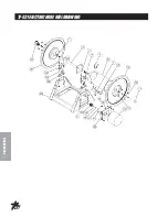
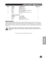
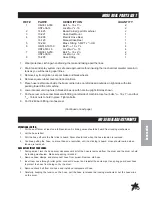
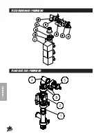
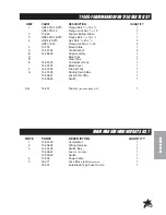
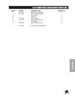
1752D PLUMBING PARTS LIST AND INSTALLATION
REF#
PART#
DESCRIPTION
QUANTITY
1
15-743
Electric ball Valve
1
2
15-742
Inlet Cover
1
3
15-740
50 Series Clamp
3
4
15-748
Reducer Coupling
1
5
15-736
#50 Elbow Coupling
1
6
15-738
Flanged Ball Valve
1
7
15-749
Hose Barb
1
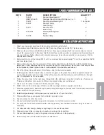
INSTALLATION INSTRUCTIONS
1. On the top of the Electric Spray Control Valve (Ref 1) you will find a cover. Remove clamp, o-ring and
cover. Install a 15-748 reducer (Ref 4) in place of the cover you just removed. Reinstall clamp and o-ring
and tighten. The cap will not be used again.
2. Install a 15-736 Elbow onto the top of the reducer with a 15-740 clamp (Ref 3) and O-ring. Rotate it 90° so
it points to the rear of the machine, then tighten clamp.
3. Install the 15-738 ball valve (Ref 6) onto the elbow using a 15-740 clamp and O-ring. Tighten with the
handle on the top or side.
4. Install the 15-749 Hose Barb (Ref 7) onto the open end of the ball valve with a 15-740 clamp and o-ring.
Tighten.
5. Route the orange
3
/
4
" hose fro the hose barb to the hose barb on the hose reel and secure with a 18-040
Hose clamp.
6. Secure the orange hose to the machine with a nylon tie strap.
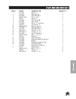
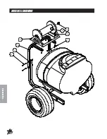
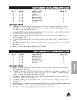
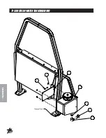
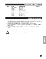
1754D PLUMBING PARTS LIST AND INSTALLATION
REF#
PART#
DESCRIPTION
QUANTITY
1
15-778
Blank Guage Port
1
2
15-738
Flanged Ball Valve
1
3
15-740
50 Series Clamp
2
4
15-736
#50 Elbow Coupling
1
5
15-749
Hose Barb
1
INSTALLATION INSTRUCTIONS
1. Between the boom control valves and the fuel tank you will find a tee fitting with a black cap on top of it.
Remove the clamp and the cap.
2. Install the 15-738 ball valve (Ref 2) onto the top of the tee using the clamp and o-ring you removed in step
1. The Handle can be positioned so it clears the other hoses by rotating it before the clamp is tightened.
Tighten clamp when ball valve is in the position you wanted.
3. Install the 15-736 Elbow (Ref 4) on top of the ball valve pointing to the back of the machine and secure
with 15-740 clamp(Ref 3) and O-ring. Tighten.
4. Install the 15-749 flanged hose barb (Ref 5) on to the open end of the elbow with a 15-740 clamp and O-
ring. Tighten.
5. Route the orange
3
/
4
" hose from the hose barb you just installed to the hose barb on the hose reel. Secure
with an 18-40 hose clamp. Secure orange hose to machine with 22-075 nylon ties.
6. You will have a reducer coupling, clamp and cap left over that you will not need.
Summary of Contents for 175GD001
Page 14: ...12 Diagrams HYDRAULICDIAGRAM ...
Page 16: ...14 Parts BODY FRAMEDRAWING ...
Page 18: ...16 Parts NOSE CONE DRAWING ...
Page 20: ...18 Parts NOSE CONE DRAWING ...
Page 22: ...20 Parts FRONT AXLE DRAWING ...
Page 24: ...22 Parts OILANDFUELTANKDRAWING ...
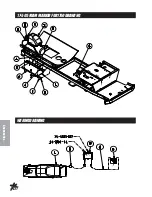
Page 26: ...24 Parts SEATPANEL DRAWING ...
Page 28: ...26 Parts ENGINE PUMPSANDEXHAUSTDRAWING ...
Page 30: ...28 Parts ENGINE PUMPSANDEXHAUSTDRAWING ...
Page 32: ...30 Parts SPRAYPUMPDRAWING ...
Page 34: ...32 Parts TANKDRAWING TURBO QUADAGITATORDRAWING ...
Page 36: ...34 Parts PARKBRAKEANDREARAXLEDRAWING ...
Page 38: ...36 Parts 15 301 ORBITROL DRAWING ...
Page 40: ...38 Parts 77 239 EATON HYDROSTATIC PUMP DRAWING DIESEL ...
Page 42: ...40 Parts 16 998 HYPRO PUMP DRAWING ...
Page 44: ...42 Accessories 1752D PLUMBING DRAWING RAVEN 440 ...
Page 46: ...44 Accessories 1754DPLUMBINGDRAWING RAVEN203 ...
Page 48: ...46 Accessories CONTROLS 1752D SYSTEM DRAWING RAVEN 440 CONTROL11754DSYSTEMDRAWING RAVEN 203 ...
Page 50: ...48 Accessories 16 524 MOTORIZEDCONTROLVALVEDRAWING ...
Page 52: ...50 Accessories 15 743MSANIFOLDVALVEDRAWING ...
Page 56: ...54 Accessories 15 493STAINLESSSTEEL18 AUTOBOOMDRAWING ...
Page 58: ...56 Accessories 10 30018 TERRAINFOLLOWINGBOOMDRAWING ...
Page 60: ...58 Accessories 10 30018 TERRAINFOLLOWINGBOOMDRAWING ...
Page 62: ...60 Accessories 10 30018 TERRAINFOLLOWINGBOOMDRAWING ...
Page 64: ...62 Accessories 17 503 20 SPRAY BOOM DRAWING ...
Page 66: ...64 Accessories 17 503 20 SPRAY BOOM DRAWING ...
Page 68: ...66 Accessories 30 00320 TERRAINFOLLOWINGBOOMDRAWING ...
Page 70: ...68 Accessories 30 003 20 TERRAINFOLLOWINGBOOMDRAWING ...
Page 72: ...70 Accessories 30 003 20TERRAINFOLLOWINGBOOMDRAWING ...
Page 74: ...72 Accessories NOZZLEASSEMBLYDRAWING ...
Page 78: ...76 Accessories 17 521ELECTRICHOSEREELDRAWING ...
Page 80: ...78 Accessories ELECTRICHOSEREELWIRINGDIAGRAM ...
Page 82: ...80 Accessories 17 507HOSEREELDRAWING ...
Page 84: ...82 Accessories HOSEREELDRAWING ...
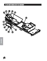
Page 86: ...84 Accessories 1752D RAVEN440 PLUMBING 1754D SSC 203 PLUMBING ...
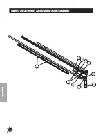
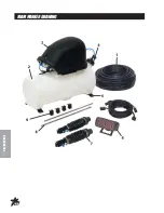
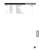
Page 88: ...86 Accessories 17 505 FOAMMARKERFOR1750DRAWING WIRINGDRAWING ...
Page 90: ...88 Accessories 17 505FOAMMARKERFOR1750DRAWING ...
Page 92: ...90 Accessories FOAMER NOZZLEMOUNT HOSEGUARDMOUNTDRAWING ...
Page 94: ...92 Accessories FOAMMARKERDRAWING ...
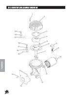
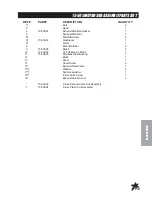
Page 96: ...94 Accessories 15 505MOTORSUBASSEMBLYDRAWING ...
Page 98: ...96 Accessories 15 511FOAMNOZZLESUBASSEMBLYDRAWING ...
Page 100: ...98 Accessories 17 506FRESHWATERTANKDRAWING ...
Page 102: ...100 Accessories 14 515WATERMETERKIT GALLONS 15 618WATERMETERKIT LITERS ...
Page 104: ...102 Accessories 15 619CHEMICALCLEANLOADSAFEFILLSYSTEM ...
Page 108: ...106 Accessories NOTES ...