22
Operation
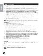
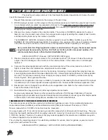
CONSOLE FIELD TEST
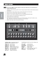
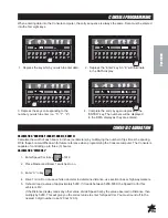
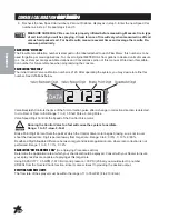
1. Drive down field or road at target speed with sprayer booms off, to verify SPEED readout on Console.
2. Turn on sprayer and booms and place the RATE 1/RATE 2/MAN switch to RATE 1. Increase or decrease
speed by one MPH (2 kph). The system should automatically correct to the target application rate.
3. If for any reason, the system is unable to correct to the desired RATE, check for an empty tank, a
plugged line, a malfunctioning pump, improper vehicle speed or a defect in the system.
4. If the system does not appear to be correcting properly, first review Initial Console Setup, then refer to
Troubleshooting in the Parts/Service Manual.
5. At the end of each row, shut off flow with the Master On/Off switch. This also shuts off area totalizer.
6. Verify area covered and volume used.
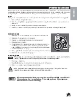
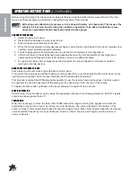
SPRAY OPERATION
(AFTER PROPER SETUP AND CALIBRATION)
1. Add
1
/
2
the amount of water required for the spray operation to tank using air gap filler.
2. Start engine, set engine speed below 2000 RPM, and engage pump after taking all previously described
safety and operation precautions.
3. Open agitator valve.
4. Add chemicals (taking all precautions described in this manual and by the chemical manufacturer).
a. Liquids may be poured directly into tank.
b. Wettable powder chemicals must be pre-mixed with water in a container to form a slurry. The mixture
is then added to the tank through the fillwell strainer.
c. Chemical in soluble packs are place into the fillwell strainer basket and dissolved by adding water
through the basket.
The balance of the water required for the spray operation is added to the tank through the fillwell strainer,
using the air gap filler. This will wash any undissolved chemical into the tank.
5. Transport to sprayer site with and agitator operating.
6. Set Engine speed between 2000-3600 RPM.
7. (Optional) Engage ground speed control.
8. Obtain desired spraying speed before activating spray with switches on spray control console.
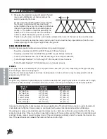
In some extreme situations, it may be necessary to decrease or completely close the flow of material to the agita-
tor system in order to maintain desired pressure. If agitation is absolutely essential, a change may have to be made
in some combination of ground speed, nozzle size or system pressure to maintain the necessary application rate.
Review the capacity of nozzles being used. Total capacity of all nozzles plus agitation system
must not exceed pumping system capabilities refer to Spraying Procedure section of this
manual. FLUSH PUMP AFTER USE
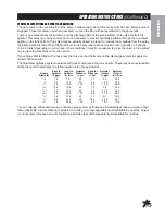
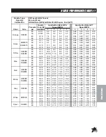
Pump
Pressure
Engine
Shaft
GPM at GPM at GPM at GPM at
Max
RPM
RPM
20psi
30psi
40psi
60psi
HP
2300
3200
70
55
5
-
1.4
2750
3800
75
71
60
10
1.8
3200
4400
80
78
72
60
3.0
Pump RPM = Engine RPM x 1.38
One of the most common causes for faulty-pump performance is corrosion inside the pump. Flush pump and
entire system with a solution that will chemically neutralize the liquid pumped. Mix according to the
manufacturer’s directions. This will dissolve most residue remaining in the pump, leaving the inside of the
pump clean for the next use.
Summary of Contents for Spray star 1602HD
Page 42: ...Part 74 17 041503...

