background image

FI 

3

34 

Liitännät 

IMUVERSION ILMAN ULOSTULO 

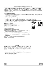
Imuversio asennetaan liittämällä liesituuletin ilman ulostuloon 
jäykällä putkella ø160 tai 125 mm, asentajan valinnan mukaan. 

Putkiliitäntä ø 160 

• Laita laippa 

10

, liesituulettimen rungon ulostuloon.

• Kiinnitä putki sopivilla puristimilla. Materiaali ei kuulu

toimitukseen.

Putkiliitäntä ø 125 

• Jos käytät putkea ø 125 mm, laita kavennuslaippa 

9

asentamaasi laippaan 

10

• Kiinnitä putki sopivilla puristimilla. Materiaali ei kuulu

toimitukseen. 

• Molemmissa tapauksissa mahdolliset aktiivihiilisuodattimet

täytyy poistaa. 

SUODATUSVERSION ILMAN ULOSTULO 

• Liitä laippa ilman ulostuloaukkoon jäykän putken kautta ø 125

tai 160 mm. 

• Putken ø 125 mm liittämistä varten liesituulettimen rungon

ulostuloaukkoon on asetettava kavennuslaippa 

9

• Kiinnitä putki sopivilla kiinnittimillä. Materiaali ei kuulu

toimitukseen. 

• Kiinnitä  suuntausritilä 

ulostuloon kahdella toimitetulla

ruuvilla 

12e 

(2,9 x 9,5). 

• Varmista, että aktiivihiilihajusuodattimet ovat paikoillaan

(Katso kappaletta Aktiivihiilisuodattimien huolto).

SÄHKÖLIITÄNTÄ 

• Liitä liesituuletin sähköverkkoon asentamalla kaksinapainen

kytkin, jonka koskettimien väli on vähintään 3 mm. 

Syöttöliitin 

Summary of Contents for T-9309-B

Page 1: ...T 9309 B Instructions Manual Käyttöohje ...

Page 2: ...2 2 INDEX RECOMMENDATIONS AND SUGGESTIONS 3 CHARACTERISTICS 6 INSTALLATION 8 USE 18 MAINTENANCE 20 SISÄLTÖ OHJEET JA SUOSITUKSET 22 MITAT JA OSAT 25 ASENNUS 27 KÄYTTÖ 37 HUOLTO 39 EN FI ...

Page 3: ...nect the extractor to the exhaust flue through a pipe of minimum diameter 120 mm The route of the flue must be as short as possible Do not connect the extractor hood to exhaust ducts carrying combustion fumes boilers fireplaces etc If the extractor is used in conjunction with non electrical appliances e g gas burning appliances a sufficient degree of aeration must be guaranteed in the room in orde...

Page 4: ... use to eliminate kitchen smells Never use the hood for purposes other than for which it has been designed Never leave high naked flames under the hood when it is in operation Adjust the flame intensity to direct it onto the bottom of the pan only making sure that it does not engulf the sides Deep fat fryers must be continuously monitored during use overheated oil can burst into flames Do not flam...

Page 5: ...r more frequently for particularly heavy usage Clean the hood using a damp cloth and a neutral liquid detergent The symbol on the product or on its packaging indicates that this product may not be treated as household waste Instead it shall be handed over to the applicable collection point for the recycling of electrical and electronic equipment By ensuring this product is disposed of correctly yo...

Page 6: ...with Controls Light Filters 2 1 Motor unit 3 1 Electric unit 4 1 Front Frame Ref Q ty Installation Components 7 1 2 Splashback Fixing Bracket 7 2 2 Hob Fixing Bracket 7 3 2 Side Bracket 12a 16 Screws 3 5 x 9 5 12b 6 Screws M4 x 8 12c 6 Screws 4 x 15 Q ty Documentation 1 Instruction Manual ...

Page 7: ...EN 7 7 Dimensions ...

Page 8: ...lation Sequence of operations Installation Drilling the Support Surface and Fitting the Hood Connections Functional Check Disposal of Packaging Drilling the Support Surface IMPORTANT The minimum distance between the opening for the hob and the one for the hood must be of at least 3 5 cm according to the strength of the material used for the working top 109 812 ...

Page 9: ...od Canopy see paragraph on Fixing the Motor Unit Insert the Hood Canopy from below into the support worktop drilled as described above With the aid of a support lift the Hood Canopy until the front comes out of the Worktop Insert the Brackets 7 2 as indicated in the figure into the slots provided and fix them with the screws 12a provided Centre the Hood Canopy with respect to the Cooking Hob slot ...

Page 10: ... must be removed and replaced at the front and the Cable with cable raceway for connection of the Motor must also be repositioned using the slot provided on each side A Insert the Hood Canopy into the cooker top drilled as described above Centre the Hood Canopy with respect to the Cooking Hob slot Fix the Hood Canopy with the 2 screws 12c provided Warning If the cooker top is made from a material ...

Page 11: ... tightening the Brackets completely make all the adjustments to allow them to rest on the lower base of the worktop to avoid deformation of the upper brackets 7 2 as shown in the figure With the aid of a spirit level set the Hood Canopy level vertically and fix it to the Lower Surface using 2 screws 12c provided Tighten the screws 12a completely ...

Page 12: ...anopy using the screws 12b provided without tightening completely Using the screws 12c provided fasten the other part of the brackets 7 3 either to the side walls of the unit or to the lower part of the cooker top 12b 7 3 12b 7 3 12c Tighten the screws 12c and 12b completely ...

Page 13: ...Subsequently according to where the air outlet opening has been created on the unit the Motor Unit can be turned by 90 at a time so as to allow the air to come out on all 4 sides in correspondence with the opening in Unit 2 Connect the connector from the Hood Canopy to the Motor Unit connection Screw the Motor Unit to the Hood Canopy using the screws 12a and 12b provided as shown in the figure ...

Page 14: ... Unit so take care not to make mistakes when connecting up Fix the Electric Unit to the Hood Canopy using the screws 12a provided The position indicated in the figure is only an option as if necessary it may also be fitted on the left of the Hood Canopy or even left free on the base of the unit if there are no structural or safety problems involved Warning Donotinstalltheproductinsuchawaythatthewi...

Page 15: ... not supplied Remove any activated charcoal filters AIR OUTLET RECIRCULATION VERSION Connect the Flange to the air outlet opening using a rigid or flexible pipe of ø125 or 160 mm To connect using a ø125 mm pipe insert the reduction Flange 9 onto the Hood canopy outlet Fasten the pipe using suitable pipe clamps The materials required to do so are not provided Fix the directional Grid 8 on the outle...

Page 16: ...ge guards from the corners of the glass Take the front Frame and insert it from above making sure that its tabs insert into the slots provided on the Hood and sliding it to the left Warning All the tabs must be inserted Use a tool hammer to tap all along the front Frame from right to left until it is completely flush A piece of wood or similar element can be inserted between the hammer and the fro...

Page 17: ...EN 1 17 Surround Suction Panel Open the Hood Door see USE Remove the 2 strips of adhesive tape fastening the panel during transport ...

Page 18: ...e speed This speed is timed to run for 6 minutes At the end of this time the systemwill return to the speed set previously It is disabled by pressing the same button again turning the motor off or closing the door Flashing LED button D Onlyworks with the Door Open Activates speed three Fixed LED button Onlyworks with the Door Open Activates Deactivates speed two Fixed LED button E Works both with ...

Page 19: ... paragraph Use Function of Button G Motor Door Closed Opens the door turns the motor on at speed one and turns the lights on at maximum intensity Door Open Brief pressure Motor On Off Pressed for 2 Seconds Closes the Door and Motor Lights Off Only with Door Open Decreases the working speed each time it is pressed Only with Door Open Increases the working speed each time it is pressed Intensive Onl...

Page 20: ...n also be washed in the dishwasher and need to be cleaned whenever button B lights up or at least once every 2 months use or more frequently if use is particularly intensive Resetting the alarm signal Turn the Lights and the Suction Motor off Press and hold button B for 2 seconds Cleaning the Filters Open the Door see USE Open the Comfort panel by pulling it Remove the Filters one at a time pushin...

Page 21: ... Activated Charcoal Filter saturation alarm DEACTIVATED CHANGING THE ACTIVATED CHARCOAL FILTER Resetting the alarm signal Turn the Lights and the Suction Motor off Press and hold button B for 2 seconds Changing the Filter Remove the comfort panel Remove the Metal grease filters Remove the metal filter stops from the grease filter and clean the saturated activated charcoal odour filter Replace the ...

Page 22: ...Liitä liesituuletin savuhormiin putkella jonka läpimitta on vähintään 120 mm Savun poistoreitin on oltava mahdollisimman lyhyt Älä liitä liesituuletinta savukanaviin joiden kautta poistetaan palamishöyryjä esimerkiksi lämmityskattilat takat jne Jos liesituuletinta käytetään yhdessä muiden kuin sähkölaitteiden esimerkiksi kaasulaitteiden kanssa on pystyttävä takaamaan riittävä huoneen tuuletus pois...

Page 23: ...seen Älä koskaan käytä liesituuletinta muuhun tarkoitukseen kuin siihen mitä varten se on suunniteltu Älä koskaan pidä korkeita liekkejä toiminnassa olevan liesituulettimen alla Säädä liekkien koko sillä tavoin että ne kohdistuvat vain kypsennysastian pohjaan Varmista etteivät liekit tule astian reunojen alta Rasvakeittimiä on valvottava jatkuvasti käytön aikana ylikuumentunut öljy voi syttyä pala...

Page 24: ...yy vaihtaa noin 4 kuukauden käytön jälkeen tai useammin jos laitetta käytetään paljon Puhdista liesituuletin kostealla liinalla ja neutraalilla pesunesteellä Merkki tuotteessa tai sen pakkauksessa osoittaa että tuotetta ei saa hävittää tavallisen kotitalousjätteen mukana Tuote täytyy toimittaa asianmukaiseen sähköisten ja elektronisten osien keräyskeskukseen Varmistamalla että tuote hävitetään oik...

Page 25: ...o johon kuuluu Kytkimet valo suodattimet 2 1 Moottoriryhmä 3 1 Sähköryhmä 4 1 Etukehys Viite Lkm Asennuksen osat 7 1 2 Takaseinän kiinnitystuki 7 2 2 Tason kiinnitystuki 7 3 2 Sivutuki 12a 16 Ruuvit 3 5 x 9 5 12b 6 Ruuvit M4 x 8 12c 6 Ruuvit 4 x 15 Lkm Asiakirjat 1 Käyttöohjeet ...

Page 26: ...FI 2 26 Mitat ...

Page 27: ...ersio Sisäinen kierto Asennustoimenpiteet Tason poraaminen ja liesituulettimen kokoaminen Liitännät Toiminnan tarkistus Pakkausten hävittäminen Tukitason poraaminen TÄRKEÄÄ Minimietäisyys keittotasoa varten tehdyn aukon ja imulaitteen aukon välillä on ainakin 3 5 cm tason valmistusmateriaalin kestävyydestä riippuen 109 812 ...

Page 28: ...amista moottoriryhmä täytyy kiinnittää liesituulettimen runkoon Katso kappaletta Moottoriryhmän kiinnittäminen Työnnä liesituulettimen runko valmiiksi porattuun tukitasoon alhaalta Nosta liesituulettimen runkoa tuen avulla kunnes etupaneeli tulee ulos tasosta Työnnä tuet 7 2 niiden aukkoihin kuten kuvassa ja kiinnitä ne toimitetuilla ruuveilla 12a Kohdista liesituulettimen runko tason aukon kohdal...

Page 29: ...en taakse kiinnitetty tulppa täytyy poistaa ja laittaa eteen Sijoita uudelleen myös johto ja vedonpoistin moottorin liitäntää varten käytä toista molemmilla puolilla olevista aukoista A Työnnä liesituulettimen runko valmiiksi porattuun tasoon Kohdista liesituulettimen runko tason aukon kohdalle Kiinnitä liesituulettimen runko 2 toimitetulla ruuvilla 12c Huomio Jos ruuveja 12c ei tason materiaalin ...

Page 30: ...la 12a Ennen tukien lopullista kiristämistä tee säädöt jotka sallivat tukien asettumisen tason alareunaan välttäen ylätukien 7 2 vääntymisen katso kuvaa Säädä liesituulettimen runko pystysuoraan vesivaa an avulla ja kiinnitä se alatasoon 2 toimitetulla ruuvilla 12c Kiristä ruuvit 12a 12c 12a 7 1 12a 7 1 ...

Page 31: ...nen Kiinnitä tuet 7 3 liesituulettimen runkoon toimitetuilla ruuveilla 12b Älä kiristä niitä Ruuvaa toimitetut ruuvit 12c tukien 7 3 toiselle puolelle kalusteen seiniin tai tason alaosaan 12b 7 3 12b 7 3 12c Kiristä ruuvit 12c ja 12b ...

Page 32: ... paikalla Moottoriryhmää voidaan sitten ilmanpoistoaukon sijainnin mukaan kääntää 90 kerrallaan jotta ilma voidaan poistaa kaikilta neljältä kalusteen sivuja vastaavalta sivulta 2 Liitä liesituulettimen rungon liitin moottoriryhmän liittimeen Ruuvaa moottoriryhmä sitten kiinni liesituulettimen runkoon toimitetuilla ruuveilla 12a ja 12b kuten kuvassa ...

Page 33: ... virhettä liitännöissä Kiinnitä sähköryhmä liesituulettimen runkoon toimitetuilla ruuveilla 12a Kuvassa näkyvä asento on vain viitteellinen Kiinnittäminen voidaan tehdä myös liesituulettimen rungon vasemmalle puolelle tai ryhmä voidaan jättää vapaana kalusteen alaosaan jos siinä ei ole rakenteellisia tai turvallisuutta koskevia esteitä Huomio Älä asenna tuotetta niin että sähkökotelo jää kosketuks...

Page 34: ...emmissa tapauksissa mahdolliset aktiivihiilisuodattimet täytyy poistaa SUODATUSVERSION ILMAN ULOSTULO Liitä laippa ilman ulostuloaukkoon jäykän putken kautta ø 125 tai 160 mm Putken ø 125 mm liittämistä varten liesituulettimen rungon ulostuloaukkoon on asetettava kavennuslaippa 9 Kiinnitä putki sopivilla kiinnittimillä Materiaali ei kuulu toimitukseen Kiinnitä suuntausritilä 8 ulostuloon kahdella ...

Page 35: ...isen aikana Poista sienisuojukset lasin kulmista Ota etukehys ja työnnä se ylhäältä alas varmistaen että kielekkeet tulevat liesituulettimen aukkoihin siirrä sitä vasemmalle Huomio Kaikkien kielekkeiden täytyy olla paikallaan Taputa etukehystä oikealta vasemmalle työkalulla vasara kunnes se tulee paikalleen Sen vahingoittumisen välttämiseksi voidaan käyttää esinettä sopivan kokoista puupalaa vasar...

Page 36: ...FI 3 36 Imupaneeli Avaa liesituulettimen paneeli Katso kappaletta Käyttö Poista 2 liimanauhaa jotka pitävät paneelia paikallaan kuljetuksen aikana ...

Page 37: ... asetettuun nopeuteen Poistetaan toiminnasta painamalla samaa painiketta sammuttamalla moottori tai sulkemalla paneeli Merkkivalopainike vilkkuu D Toimii vain kun paneeli on auki Aktivoi kolmannen nopeuden Merkkivalopainike palaa Toimii vain kun paneeli on auki Aktivoi poistaa käytöstä toisen nopeuden Merkkivalopainike palaa E Toimii paneelin ollessa kiinni tai auki kun moottori ja valot Off 4 sek...

Page 38: ...ta Käyttö Painikkeen G toiminta Moottori Paneeli kiinni Käynnistää moottorin ensimmäisellä nopeudella ja valot suurimmalla teholla Paneeli auki Lyhyt painallus Moottori On Off Kun painiketta painetaan 2 sekunnin ajan Sulkee paneelin ja valot ja moottori Off Vain kun paneeli on auki Alentaa käyttönopeutta jokaisella painalluksella Vain kun paneeli on auki Lisää käyttönopeutta jokaisella painallukse...

Page 39: ...lliset rasvasuodattimet Ne voidaan pestä astianpesukoneessa Ne täytyy pestä kun painikkeen B merkkivalo palaa tai vähintään 2 käyttökuukauden välein tai useammin jos niitä käytetään paljon Hälytyksen kuittaus Sammuta valo ja imumoottori Paina painiketta B 2 sekunnin ajan Suodattimien puhdistus Avaa paneeli Katso kappaletta Käyttö Vedä Comfort Panel auki Poista suodattimet yksi kerrallaan työntämäl...

Page 40: ... Aktiivihiilisuodattimen hälytys on POISTETTU KÄYTÖSTÄ AKTIIVIHIILIHAJUSUODATTIMEN VAIHTAMINEN Hälytyksen kuittaus Sammuta valo ja imumoottori Paina painiketta B 2 sekunnin ajan Suodattimen vaihtaminen Irrota Comfort panel Poista metalliset rasvasuodattimet Poista rasvasuodattimesta metallisuodattimien pidike ja puhdista täyttynyt aktiivihiilihajusuodatin Asenna puhdistettu aktiivihiilihajusuodati...

Page 41: ......

Page 42: ......

Page 43: ......

Page 44: ...991 0282 427_ver6 ...

Reviews: