background image

Instructions for the installer 


2.2


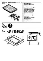
Attachment to support structure, flush-mounting model  

Create an opening with the dimensions 
shown in the figure in the work surface, 
observing a minimum distance of  50 mm 
from the rear edge. 

1) 

The lower part of the protective cover 
must be fully accessible when the 
appliance is installed. This appliance can 
be installed next to walls that are higher 
than the work surface, as long as the 
distance "X" is kept, as shown in the 
figure, to avoid damage from overheating. 
Make sure there is a minimum of 750 mm (Fig. 1) between the gas rings and any shelf 
that may be installed directly above them. This type of appliance also requires a cut 3 
mm deep in the work-top with the dimensions shown in figure 4 (detail A, figure 2). 
Before positioning the hob, position the adhesive sponge material “E” supplied over 
the milled surface (fig. 2). Now place the hob on the cut in the work-top and use the 
screws and fixing brackets (sequence shown in Fig. 3) to secure the hob to the 
supporting structure, adjusting it until perfectly horizontal. Do not fit the brackets 
shown in fig. 3 until the hob has been set in place. 

2) 


3)


4) 

Mill to this depth for laminated worktops of less
than 3mm thickness.


Apply a layer of “waterproof primer” to the milled surface. 


Summary of Contents for PGA75F3

Page 1: ...MAINTENANCE ___________________________ 19 8 PROBLEMS AND CAUSES ________________________________ 20 THESE INSTRUCTIONS ARE VALID ONLY FOR END USER COUNTRIES WHOSE IDENTIFICATION SYMBOLS APPEAR ON THE...

Page 2: ...VE THE PACKAGING MATERIALS UNATTENDED IN THE HOME ENVIRONMENT SEPARATE THE DIFFERENT WASTE MATERIALS FROM THE PACKAGING AND DELIVER THEM TO THE NEAREST COLLECTION CENTRE FOR RECYCLABLE WASTE REGULATIO...

Page 3: ...LIANCE IS DESIGNED FOR USE BY ADULTS DO NOT ALLOW CHILDREN TO GO NEAR OR PLAY WITH IT REPLACED APPLIANCES MUST BE TAKEN TO A SPECIAL GARBAGE COLLECTION CENTRE WHERE THIS APPLIANCE IS INSTALLED IN MARI...

Page 4: ...the appliance and the wall as shown in the figure to avoid damage from overheating Make sure there is a minimum of 750 mm between the gas rings and any shelf that may be installed directly above them...

Page 5: ...750 mm Fig 1 between the gas rings and any shelf that may be installed directly above them This type of appliance also requires a cut 3 mm deep in the work top with the dimensions shown in figure 4 d...

Page 6: ...res in mm Caution surface temperature underneath may exceed 125 degrees C To avoid a hazard under bench access must be restricted Refer to installation instruction IMPORTANT when installing the applia...

Page 7: ...er in no case shall the clearance between the highest part of the hob of the cooking appliance and a range hood be less than 600 mm or for an overhead exhaust fan 750 mm Any other downward facing comb...

Page 8: ...part of the appliance where cooking normally takes place and does not include those parts of the appliance containing control knobs 3 For definition of hob see Clause 1 4 64 4 For definition of trivet...

Page 9: ...ds connected to a natural draught flue with certain efficiency or by means of forced aspiration An efficient aspiration system requires careful planning by a specialist capable of installing it respec...

Page 10: ...n to allow the gas to be turned off and disconnected for servicing and removal of the appliance as required from the gas supply Before the appliance is operated make certain all relevant parts are pla...

Page 11: ...the appliance Do not use reducers adapters or shunts If the power cable is to be replaced the wire section on the new cable must not be less than 0 75 mm 2 3 x 0 75 cable bearing in mind that the end...

Page 12: ...have to replace the nozzles then adjust the minimum flame on the gas taps For nozzle replacement and burner adjustment operate as described in the following paragraph 4 1 Replacement of nozzles on the...

Page 13: ...nsumption MJ h Injector mm Auxiliary 1 3 9 0 54 Semi rapid 2 6 3 0 68 Ultra Rapid 3 13 5 1 00 Burner NG 1 0 kPa Nominal gas Consumption MJ h Injector mm Auxiliary 1 3 9 0 90 Semi rapid 2 7 5 1 20 Ultr...

Page 14: ...5 1 Regulation of minimum for town gas and natural gas Light the burner and set it at minimum position Remove the knob and turn the regulation screw inside or next to the gas tap pin depending on the...

Page 15: ...each knob indicates the relative burner The device is fitted with electronic ignition Simply press and turn the knob counter clockwise to the high flame symbol until the burner is ignited In models w...

Page 16: ...boiling point lower the flame so that it does not boil over To avoid burns or damage to the worktop all receptacles or griddle plates must be placed within the perimeter of the cooking hob When using...

Page 17: ...c scourers or sharp scrapers be used they will damage the surface Use normal non abrasive products for steel and a wooden or plastic tool if necessary Rinse thoroughly and dry with a soft cloth or cha...

Page 18: ...o be cleaned and re greased this operation must be carried out by an authorised person 8 PROBLEMS AND CAUSES Each of the following cases is caused by an abnormal operation of the appliance and should...

Page 19: ......

Page 20: ...914773032 C...

Reviews: