background image

Cleaning and maintenance

30

4. Clean the external glass pane and the 

panes removed previously. Use 
absorbent kitchen roll. In case of 
stubborn dirt, wash with a damp sponge 
and neutral detergent.

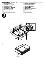
5. Refit the panes in the reverse order in 

which they were removed.

6. Reposition the internal glass pane. Take 

care to centre and insert the 4 pins into 
their housings in the oven door by 
applying slight pressure.

4.5 Cleaning the oven cavity

In order to keep your oven in the best 
possible condition, clean it regularly after 
letting it cool down.
Avoid letting food residue dry inside the 
oven cavity, as this could damage the 
enamel.
Take out all removable parts.

For easier cleaning, we recommend 
removing:
• The door
• The rack/tray support frames
• The oven seal.

The oven should be operated at 
the maximum temperature for 
about 15-20 minutes after the use 
of specific products, to burn off the 
residues left inside the oven.

Summary of Contents for CX61VMLS8

Page 1: ... oven 19 3 6 Programmer clock 21 3 7 Cooking advice 24 4 Cleaning and maintenance 27 4 1 Instructions 27 4 2 Cleaning the surfaces 27 4 3 Cleaning the hob 28 4 4 Cleaning the door 28 4 5 Cleaning the oven cavity 30 4 6 Extraordinary maintenance 33 5 Installation 35 5 1 Gas connection 35 5 2 Adaptation to different types of gas 38 5 3 Positioning 43 5 4 Instructions for the installer 48 5 5 Electri...

Page 2: ...or their safety Children must not play with the appliance Keep children under the age of eight at a safe distance unless they are constantly supervised Keep children under the age of 8 away from the appliance when it is in use Cleaning and maintenance must not be carried out by unsupervised children Make sure that the flame spreader crowns are correctly positioned in their housings with their resp...

Page 3: ...LAMMABLE MATERIALS IN THE STORAGE COMPARTMENT IF PRESENT OR NEAR THE APPLIANCE DO NOT USE AEROSOLS IN THE VICINITY OF THIS APPLIANCE WHILST IT IS IN USE Switch off the appliance immediately after use DO NOT MODIFY THIS APPLIANCE Always use any necessary required personal protective equipment PPE before performing any work on the appliance installation maintenance positioning or movement Before per...

Page 4: ...uld be released as these could then heat up and catch fire Be very careful Never leave objects on the cooking surface DO NOT FOR ANY REASON USE THE APPLIANCE AS A SPACE HEATER Do not spray any spray products near the oven Do not use plastic cookware or containers when cooking food Do not put sealed tins or containers in the oven Remove all trays and racks which are not required during cooking Do n...

Page 5: ...e or corrosive detergents e g scouring powders stain removers and metallic sponges on glass parts Do not wash removable parts such as the hob pan support grids flame spreader crowns and burner caps in the dishwasher Never use the oven door to lever the appliance into place when fitting Avoid exerting too much pressure on the oven door when open Do not use the handle to lift or move the appliance I...

Page 6: ...ion performed by authorised technical personnel The appliance must be connected to earth in compliance with electrical system safety standards Use cables withstanding a temperature of at least 90 C The tightening torque of the terminal board screws for the power supply wires must be 1 5 2 Nm For this appliance Ensure that the appliance is switched off before replacing the bulb Do not rest any weig...

Page 7: ...part of the appliance and must therefore be kept in its entirety and within the user s reach for the whole working life of the appliance Read this user manual carefully before using the appliance 1 6 Disposal This appliance must be disposed of separately from other waste Directives 2002 95 EC 2002 96 EC 2003 108 EC The appliance does not contain substances in quantities sufficient to be considered...

Page 8: ...quence of instructions for use Standalone instruction Plastic packaging Danger of suffocation Do not leave the packaging or any part of it unattended Do not let children play with the plastic bags Instructions General information on this user manual on safety and final disposal Description Description of the appliance and its accessories Use Information on the use of the appliance and its accessor...

Page 9: ...Description 11 EN 2 Description 2 1 General Description 1 Upstand 2 Hob 3 Control panel 4 Left light 5 Seal 6 Door 7 Fan Rack tray support frames ...

Page 10: ...o select the cooking temperature Turn the knob clockwise to the required value between the minimum and maximum setting 2 Indicator light The indicator light comes on to indicate that the oven is heating up It turns off as soon as it reaches the set temperature It flashes regularly to indicate that the temperature set inside the oven is kept constant ...

Page 11: ...the knobs to the position to turn off the burners 2 4 Other parts Shelves The appliance features shelves to position trays and racks at different heights The insertion heights are indicated from the bottom upwards see 2 1 General Description Cooling fan The fan cools the appliance and comes into operation during cooking The fan causes a steady outflow of air that exits from the rear of the applian...

Page 12: ...zas and baked desserts Tray rack To be placed over the top of the tray for cooking foods which may drip Trivet Useful when using small cookware WOK support Useful when using a wok The oven accessories intended to come into contact with food are made of materials that comply with the provisions of current legislation Original supplied and optional accessories can be requested to Authorised Assistan...

Page 13: ...reful High temperature inside the storage compartment Danger of burns Do not open the storage compartment when the appliance is on and still hot The items inside the storage compartment could be very hot after using the appliance Do not use it for storing flammable items such as cloths paper etc Improper use Risk of damage to surfaces Do not cover the bottom of the oven cavity with aluminium or ti...

Page 14: ...he gas cocks If the appliance does not work properly contact your local Authorised Service Centre First use 1 Remove any protective film from the outside or inside of the appliance including accessories 2 Remove any labels apart from the technical data plate from the accessories and from the oven cavity 3 Remove and wash all the appliance accessories see 4 Cleaning and maintenance 4 Heat the empty...

Page 15: ...separately from the food which is being cooked Racks and trays Racks and trays have to be inserted into the side guides until they come to a complete stop The mechanical safety locks that prevent the rack from being removed accidentally must face downwards and towards the back of the oven cavity Gently insert racks and trays into the oven until they come to a stop Clean the trays before using them...

Page 16: ...b pressed in longer Correct positioning of the flame spreader crowns and burner caps Before lighting the hob burners make sure that the flame spreader crowns are correctly positioned in their housings with their respective burner caps Make sure that the holes 1 in the flame spreader crowns are aligned with the igniters 3 and thermocouples 2 Practical tips for using the hob For better burner effici...

Page 17: ...t for all types of roasts bread and cakes and in any case particularly suitable for fatty meats such as goose and duck Fan lower element The combination of the fan with just the lower heating element allows cooking to be completed more rapidly This system is recommended for sterilising or for finishing off the cooking of foods which are already well cooked on the surface but not inside which there...

Page 18: ...n of heat It will be possible for instance to cook fish vegetables and biscuits simultaneously on different levels without odours and flavours mingling Eco This function is particularly suitable for cooking on a single shelf with low energy consumption Ideal for cooking meat fish and vegetables It is not recommended for leavened foods To obtain maximum energy savings and reduce cooking times it is...

Page 19: ...tes flashes 2 The time can be set using the or key Keep the key pressed in to increase or decrease rapidly 3 Press the key or wait 5 seconds The dot between the hours and the minutes stops flashing 4 The symbol on the display indicates that the appliance is ready to start cooking Ensure that the programmer clock shows the cooking duration symbol otherwise it will not be possible to turn on the ove...

Page 20: ...ting elements will be deactivated On the display the symbol turns off the symbol flashes and the buzzer sounds 5 To turn off the buzzer just press any key of the programmer clock 6 Press the and keys at the same time to reset the programmer clock Timed cooking is the function which allows a cooking operation to be started and then ended after a specific length of time set by the user It is not pos...

Page 21: ... and the buzzer sounds 6 To turn off the buzzer just press any key of the programmer clock 7 Press the and keys at the same time to reset the programmer clock Adjusting the buzzer volume The buzzer volume can be set to 3 different levels When the buzzer is in operation press the key to change the setting Deleting the set data Press the and keys at the same time to reset the programs set Then switc...

Page 22: ...ht cooking time will be greater for cooking a whole piece than when it is cut into smaller pieces Advice for cooking meat Cooking times vary according to the thickness and quality of the food and to consumer taste Use a meat thermometer when roasting meat or simply press on the roast with a spoon If it is hard it is ready If not it needs another few minutes cooking Advice for cooking with the Gril...

Page 23: ...perature by about 10 C selecting a longer cooking time if necessary The cooking time for meringues and choux pastry will vary depending on the size Advice for defrosting and proving Place frozen foods without their packaging in a lidless container on the first shelf of the oven Avoid overlapping the food To defrost meat use the rack placed on the second level and a tray on the first level In this ...

Page 24: ...ith grill 4 260 10 10 Bacon 0 7 Grill 5 260 7 8 Pork fillet 1 5 Fan with grill 4 260 10 5 Beef fillet 1 Grill 5 260 10 7 Salmon trout 1 2 Turbo Circulaire 2 150 160 35 40 Monkfish 1 5 Turbo Circulaire 2 160 60 65 Turbot 1 5 Turbo Circulaire 2 160 45 50 Pizza 1 Turbo Circulaire 2 260 8 9 Bread 1 Circulaire 2 190 200 25 30 Focaccia 1 Turbo Circulaire 2 180 190 20 25 Bundt cake 1 Circulaire 2 160 55 ...

Page 25: ...dues of sugary foods such as jam to set inside the oven If left to set for too long they might damage the enamel lining of the oven Improper use Risk of damage to surfaces Do not use steam jets to clean the appliance Do not use cleaning products containing chlorine ammonia or bleach on parts made of steel or that have metallic surface finishes e g anodizing nickel or chromium plating Do not use ab...

Page 26: ...ir housings with their respective burner caps Igniters and thermocouples For correct operation the igniters and thermocouples must always be perfectly clean Check them frequently and clean them with a damp cloth if necessary Remove any dry residues with a wooden toothpick or a needle 4 4 Cleaning the door Removing the door For easier cleaning it is recommended to remove the door and place it on a ...

Page 27: ...Use absorbent kitchen roll In case of stubborn dirt wash with a damp sponge and an ordinary detergent Removing the internal glass panes For easier cleaning the internal glass panes of the door can be removed 1 Remove the internal glass pane by pulling the rear part gently upwards following the movement indicated by the arrows 1 This way the 4 pins attached to the glass detach from their housings i...

Page 28: ...sings in the oven door by applying slight pressure 4 5 Cleaning the oven cavity In order to keep your oven in the best possible condition clean it regularly after letting it cool down Avoid letting food residue dry inside the oven cavity as this could damage the enamel Take out all removable parts For easier cleaning we recommend removing The door The rack tray support frames The oven seal The ove...

Page 29: ... to put the guide frames back in Vapor Clean Preliminary operations Before starting the Vapor Clean cycle Completely remove all accessories from inside the oven The upper guard can be left inside the oven Pour approx 40 cc of water onto the floor of the oven Make sure it does not overflow out of the cavity Vapor Clean is an assisted cleaning procedure which facilitates the removal of dirt Thanks t...

Page 30: ... towards the deflector Close the door Vapor Clean cycle setting 1 Turn the function knob to the symbol and the temperature knob to the symbol 2 Set a cooking time of 18 minutes using the programmer clock 3 At the end of the cooking time the timer will switch the oven heating elements off and the buzzer will start to sound We recommend spraying approx 20 times at the most ...

Page 31: ...at the oven is dried using a fan assisted function at 160 C for approximately 10 minutes 4 6 Extraordinary maintenance Installing and removing the seal To remove the seal Release the clips located in the 4 corners and pull the seal outwards To refit the seal Hook the clips in the 4 corners onto the seal Seal maintenance tips The seal should be soft and elastic To keep the seal clean use a non abra...

Page 32: ...bulb 5 Replace the light bulb with one of the same type 40W 6 Refit the cover Ensure the moulded part of the glass A is facing the door 7 Press the cover completely down so that it attaches perfectly to the bulb support Live parts Danger of electrocution Unplug the appliance Use protective gloves Pay attention not to scratch the oven cavity enamel Do not touch the halogen light bulb directly with ...

Page 33: ...arp objects or sharp corners If the hose is not perfectly airtight and leaks gas do not try to repair it replace it with a new hose verify that the hose is not past its expiry date serigraphed on the hose itself Make the connection to the gas mains using a rubber hose whose specifications comply with current standards verify that the reference standard is stamped on the hose Gas leak Danger of exp...

Page 34: ...tions comply with the applicable standard Carefully screw the connector 3 to the gas connector 1 of the appliance placing the seal 2 between them Connection with a steel hose with bayonet fitting Carry out the connection to the gas mains using a steel hose with bayonet fitting compliant with B S 669 Apply insulating material to the thread of the gas hose connector 4 and then tighten the adapter 3 ...

Page 35: ...rds in force The room where the appliance is installed must have enough air flow for the regular combustion of gas and the necessary air change in the room itself The air vents protected by grilles must be the right size to comply with current regulations and positioned so that no part of them is obstructed not even partially The room must be kept adequately ventilated in order to eliminate the he...

Page 36: ... fan 5 2 Adaptation to different types of gas In case of operation with other types of gas the burner nozzles must be changed and the minimum flame adjusted on the gas cocks Replacing nozzles 1 Remove the pan supports burner caps and flame spreader crowns to access the burner cups 2 Replace the nozzles using a 7 mm socket wrench according to the type of gas to be used see the Burner and nozzle cha...

Page 37: ... go out Repeat the operation on all gas cocks Adjusting the minimum setting for LPG Tighten the screw located at the side of the cock spindle clockwise all the way Lubricating the gas cocks Over time the gas cocks may become difficult to turn and get blocked Clean them internally and replace the lubrication grease Following adjustment to a gas other than the one originally set in the factory repla...

Page 38: ...25 1 G25 1 25 mbar 5 Natural Gas G25 G25 20 mbar 6 Natural Gas G2 350 G2 350 13 mbar 7 LPG G30 31 G30 31 28 37 mbar G30 31 30 37 mbar G30 31 30 30 mbar 8 LPG G30 31 G30 31 37 mbar 9 LPG G30 31 G30 31 50 mbar 10 Town Gas G110 G110 8 mbar It is possible to identify the available gas types based on the country the appliance is to be installed in Refer to the heading number to identify the correct val...

Page 39: ...ity kW 1 05 1 8 3 5 Nozzle diameter 1 100 mm 72 94 138 Pre chamber printed on nozzle F1 Y F3 Reduced flow rate W 400 500 1600 4 Natural Gas G25 1 AUX SR UR 3c Rated heating capacity kW 1 05 1 8 3 5 Nozzle diameter 1 100 mm 77 100 145 Pre chamber printed on nozzle F1 Y F3 Reduced flow rate W 400 500 1600 5 Natural Gas G25 AUX SR UR 3c Rated heating capacity kW 1 05 1 8 3 5 Nozzle diameter 1 100 mm ...

Page 40: ...Nozzle diameter 1 100 mm 50 65 91 Pre chamber printed on nozzle Reduced flow rate W 450 550 1600 Rated flow rate G30 g h 80 131 255 Rated flow rate G31 g h 79 129 250 9 LPG G30 31 AUX SR UR 3c Rated heating capacity kW 1 05 1 8 3 5 Nozzle diameter 1 100 mm 43 58 75 Pre chamber printed on nozzle H2 M F4 Reduced flow rate W 400 500 1600 Rated flow rate G30 g h 76 131 255 Rated flow rate G31 g h 75 1...

Page 41: ...re the correct clearance is left Depending on the type of installation this appliance belongs to classes A Class 1 Free standing appliance Heavy appliance Crushing hazard Position the appliance into the cabinet cut out with the help of a second person Pressure on the open door Risk of damage to the appliance Never use the oven door to lever the appliance into place when fitting Avoid exerting too ...

Page 42: ...nce Appliance overall dimensions 1 Minimum distance from side walls or other flammable material 2 Minimum cabinet width A The appliance must be installed by a qualified technician and according to the regulations in force A 600 mm B 600 mm C1 min 150 mm D 900 915 mm H 750 mm I 450 mm L2 600 mm ...

Page 43: ...or gas connections screw the four adjustable legs supplied with the appliance The appliance must sit level on the floor to ensure stability Screw or unscrew the bottom part of the leg until the appliance is stable and level on the floor A 124 B 32 C 42 D 628 F min 105 Max 160 H 770 L 598 Heavy appliance Risk of damage to the appliance Insert the front legs first and then the rear ones ...

Page 44: ... of the appliance 2 Adjust the height of the 4 legs 3 Assemble the fastening bracket 4 Align the base of the hook on the fastening bracket with the base of the slot on the wall fastening plate The anti tip devices must be installed in order to prevent the appliance from tipping over ...

Page 45: ... side of the appliance to the bracket holes 7 Move the bracket onto the wall and mark the position of the holes to be drilled in the wall 8 After drilling the holes in the wall use wall plugs and screws to fasten the bracket to the wall 9 Push the cooker towards the wall and at the same time insert the bracket in the plate fastened to the rear of the appliance ...

Page 46: ...mage this part of the appliance which may void the manufacturer s warranty Use soap and water to check for gas leaks on all connections DO NOT use naked flames to find leaks Turn on all the burners separately and at then all together to make sure that the gas valve burner and ignition are working properly Turn the burner knobs to the minimum position and check that the flame is stable for each ind...

Page 47: ...ppliance and in an easily reachable position Connection with plug and socket Make sure that the plug and socket are of the same type Avoid using adapters and shunts as these could cause overheating and a risk of burns Power voltage Danger of electrocution Have the electrical connection performed by authorised technical personnel Use personal protective equipment The appliance must be connected to ...

Page 48: ......

Reviews: