background image

Installation

47

EN

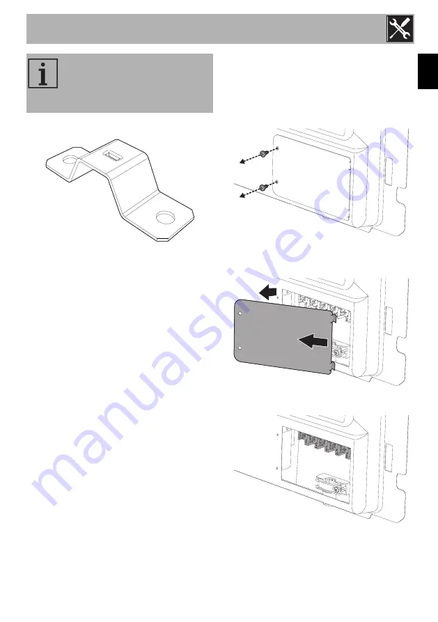
Metal cable clamp

If you use a 

3 x 10 mm²

 cable, you should 

replace the plastic cable clamp with the 
metal cable clamp provided.

Fixed connection

Fit the power line with an all-pole 
disconnection switch, with a clearance 
between its contacts that allows the 
complete disconnection as per the 
overvoltage category III, in compliance 
with the installation regulations.

Access to the terminal board

To connect the power supply cable, access 
to the terminal board on the rear cover:
1. Remove the screws securing the lid to 

the rear cover.

2. Slightly turn the lid and remove it from its 

housing.

3. Install the power supply cable.

The aforementioned power cables 
are sized taking into account the 
coincidence factor (in compliance 
with standard EN 60335-2-6).

Summary of Contents for BG91IAN2

Page 1: ...accessories 17 3 2 Using the hob 18 3 3 Using the storage compartment 23 3 4 Using the oven 23 3 5 Cooking advice 25 3 6 Programmer clock 27 4 Cleaning and maintenance 32 4 1 Cleaning the hob 33 4 2...

Page 2: ...dren under the age of 8 away from the appliance when it is in use Cleaning and maintenance must not be carried out by unsupervised children Be aware of how rapidly the cooking zones heat up Do not pla...

Page 3: ...ntions according to the standards in force Do not try to repair the appliance yourself or without the intervention of a qualified technician If the power supply cable is damaged contact technical supp...

Page 4: ...over or spill remove the excess from the hob Take care not to spill acid substances such as lemon juice or vinegar on the hob Do not put empty pans or frying pans on switched on cooking zones If crac...

Page 5: ...ance must be connected to ground in compliance with electrical system safety standards Use cables withstanding a temperature of at least 90 C The tightening torque of the screws of the terminal board...

Page 6: ...brand name of the appliance Do not remove the identification plate for any reason 1 5 This user manual This user manual is an integral part of the appliance and must therefore be kept in its entirety...

Page 7: ...ons 1 Sequence of instructions for use Standalone instruction Plastic packaging Danger of suffocation Do not leave the packaging or any part of it unattended Do not let children play with the plastic...

Page 8: ...Keep the inside of the oven clean at all times 1 9 Information for European Control Bodies Fan forced mode the ECO function used to define the energy efficiency class complies with the specifications...

Page 9: ...Description 11 EN 2 Description 2 1 General Description 1 Cooking hob 2 Control panel 3 Light bulb 4 Seal 5 Door 6 Fan 7 Storage compartment Rack tray support frames...

Page 10: ...of the pan Rapid heating speed Reduced danger of burns as the cooking surface is only heated under the base of the pan foods which overflow do not stick Zone Outside diameter mm Max power draw W Powe...

Page 11: ...eating up It turns off as soon as it reaches the set temperature It flashes regularly to indicate that the temperature set inside the oven is kept constant 4 Function knob The oven s various functions...

Page 12: ...the function Cooling fan The fan cools the ovens and comes into operation during cooking The fan causes a steady outflow of air that exits from the rear of the appliance and which may continue for a b...

Page 13: ...ich may drip The accessories intended to come into contact with food are made of materials that comply with the provisions of current legislation Supplied and optional accessories can be requested to...

Page 14: ...ry hot after using the oven Improper use Risk of damage to surfaces Do not cover the bottom of the oven cavity with aluminium or tin foil sheets If you wish to use greaseproof paper place it so that i...

Page 15: ...cks that prevent the rack from being taken out accidentally have to face downwards and towards the oven back High temperature inside the storage compartment during use Danger of fire or explosion Do n...

Page 16: ...amic and terracotta cookware To see whether the pan is suitable bring a magnet close to the bottom if it is attracted the pan is suitable for induction cooking If you do not have a magnet you can put...

Page 17: ...an base is indicated by the square image on the cooking zone Pans with smaller diameters risk not being detected and therefore not activating the inductor Limiting the cooking duration The hob has an...

Page 18: ...he power in the cooking zone can be adjusted to various levels The table shows the levels suitable for various types of cooking see booster function Residual heat If the cooking zone is still hot afte...

Page 19: ...er function is always enabled and has to be disabled manually using the corresponding knob Power control The hob is fitted with a power control module that optimises limits consumption If the overall...

Page 20: ...e rear left and rear right cooking zone displays will indicate the power levels 4 and 8 5 Release the knobs 6 Turn and hold both knobs anti clockwise again The rear left and rear right cooking zone di...

Page 21: ...handle towards you It can be used to store cookware or metallic objects necessary when using the appliance 3 4 Using the oven Switching on the oven To switch on the oven 1 Select the cooking function...

Page 22: ...pyrolytic models the special defrost and proving functions are brought together under the same function Small grill Using only the heat released from the central element this function allows you to gr...

Page 23: ...eral levels as long as they need the same temperatures and same type of cooking Hot air circulation ensures instant and even distribution of heat It will be possible for instance to cook fish vegetabl...

Page 24: ...the cooking time put a toothpick into the highest point of the dessert If the dough does not stick to the toothpick the dessert is cooked If the dessert collapses when it comes out of the oven on the...

Page 25: ...p the key pressed in to increase or decrease rapidly 3 Wait 7 seconds The dot between the hours and the minutes stops flashing 4 The symbol on the display indicates that the appliance is ready to star...

Page 26: ...grammer clock keys 7 Press the clock key to reset the programmer clock Programmed cooking 1 Set the cooking time as described in the previous point Timed cooking 2 Hold the menu key down for 2 seconds...

Page 27: ...of cooking the heating elements will be deactivated On the display the symbol turns off the symbol flashes and the buzzer sounds 10 Return the function and temperature knobs to 0 11 To turn off the bu...

Page 28: ...buzzer off Modifying the set data 1 Press the clock key 2 Use the value increase and value decrease keys to set the number of minutes required Deleting the set data 1 Press the clock key 2 Hold down...

Page 29: ...ll 4 MAX 15 5 Spare ribs 1 5 Fan with grill 4 MAX 10 10 Bacon 0 7 Grill 5 MAX 7 8 Pork fillet 1 5 Fan with grill 4 MAX 10 5 Beef fillet 1 Grill 5 MAX 10 7 Salmon trout 1 2 Turbo Fan assisted 2 150 160...

Page 30: ...to surfaces Do not use steam jets to clean the appliance Do not use cleaning products containing chlorine ammonia or bleach on parts made of steel or that have metallic surface finishes e g anodizing...

Page 31: ...ents They are difficult to remove using conventional cleaning products It may be necessary to repeat the cleaning process several times Use of corrosive detergents or rubbing of pan bases can wear awa...

Page 32: ...th sides with both hands lift it forming an angle of around 30 and remove it 3 To reassemble the door put the hinges in the relevant slots in the oven making sure that grooved sections A are resting c...

Page 33: ...rows 1 4 Pull the internal glazing pane from the front strip 2 to remove it from the door 5 Remove the intermediate glass pane by lifting it upwards 6 Clean the external glass pane and the previously...

Page 34: ...frames The seal Removing racks trays support frames Removing the rack tray support frames enables the sides to be cleaned more easily To remove the rack tray support frames Pull the frame towards the...

Page 35: ...upwards downwards and towards the deflector Close the door Vapor Clean is an assisted cleaning procedure which facilitates the removal of dirt Thanks to this process it is possible to clean the inside...

Page 36: ...clock dial will flash End of the Vapor Clean cycle 4 Open the door and wipe away the less stubborn dirt with a microfibre cloth 5 Use a non scratch sponge with brass filaments on hard to remove deposi...

Page 37: ...e light bulb 5 Fit the new light bulb 6 Refit the cover Ensure the moulded part of the glass A is facing the door 7 Press the cover down as far as it will go so that it attaches completely to the bulb...

Page 38: ...located in the 4 corners and in the centre then pull the seal outwards To refit the seal Hook the clips located in the 4 corners and in the centre onto the seal Seal maintenance tips The seal should b...

Page 39: ...ion manual to ensure the correct clearance is left Depending on the type of installation this appliance belongs to classes A Class 1 Free standing appliance Heavy appliance Crushing hazard Position th...

Page 40: ...ce Appliance overall dimensions 1 Minimum distance from side walls or other flammable material 2 Minimum cabinet width A The appliance must be installed by a qualified technician and according to the...

Page 41: ...ctrical connections screw on the four feet supplied with the appliance The appliance must sit level on the floor to ensure stability Screw or unscrew the bottom part of the foot until the appliance is...

Page 42: ...of the appliance 2 Adjust the height of the 4 feet 3 Assemble the fastening bracket 4 Align the base of the hook on the fastening bracket with the base of the slot on the wall fastening plate The anti...

Page 43: ...side of the appliance to the bracket holes 7 Move the bracket onto the wall and mark the position of the holes to be drilled in the wall 8 After drilling the holes in the wall use wall plugs and screw...

Page 44: ...ree core cable 220 240 V 3 4 x 4 mm four core cable 220 240 V 1N 3 x 10 mm three core cable 380 415 V 2N 4 x 4 mm four core cable 380 415 V 3N 5 x 1 5 mm five core cable Power voltage Danger of electr...

Page 45: ...te disconnection as per the overvoltage category III in compliance with the installation regulations Access to the terminal board To connect the power supply cable access to the terminal board on the...

Page 46: ...e power cable The appliance must be installed according to the installation diagrams If the appliance does not work correctly after having carried out all the checks contact your local Authorised Serv...

Reviews: