


Z_ISE3-TF2Z043EN
Page 2 of 3
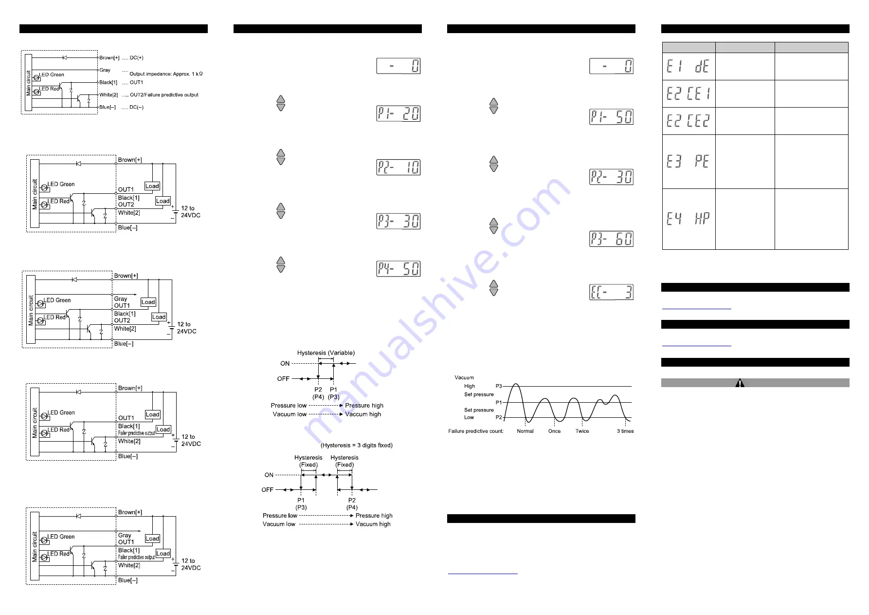
5 Wiring (continued)
5.3 Wiring diagram
5.4 Internal circuit and wiring
ZSE3 / ISE3(L)-#-21
Switch output, NPN open collector output, 2 outputs, Max. 30 V, 80 mA
ZSE3 / ISE3(L)-#-22
Switch output, NPN open collector output, 2 outputs, Max. 30 V, 80 mA
Analogue output: 1 to 5 V, Output impedance: Approx. 1 k
Ω
ZSE3 / ISE3(L)-#-23
Switch output, NPN open collector output, 1 output, Max. 30 V, 80 mA
Failure predictive output, NPN open collector output, 1 output.
ZSE3 / ISE3(L)-#-24
Switch output, NPN open collector output, 1 output, Max. 30 V, 80 mA
Failure predictive output, NPN open collector output, 1 output.
Analogue output: 1 to 5 V, Output impedance: Approx. 1 k
Ω
6 Pressure Setting
6.1 2 output type
6.2 Output method
•
Hysteresis mode (P1
≥
P2, P3
≥
P4)
•
Window comparator mode (P1
<
P2, P3
<
P4)
•
Hysteresis mode (same as for positive pressure use) When the value
of hysteresis is set to 2 digits or less, the switching output might chatter
due to fluctuation of the input pressure around its set point.
•
Window comparator mode (same as for positive pressure use) since
the hysteresis will be 3 digits, separate P1 from P2 (in case of 2-output
type, same as for P3 and P4) by 7 digits or more.
* 1 digit is the minimum pressure display unit.
6 Pressure Setting (continued)
6.3 1 Output type with Failure Predictive function
6.4 Failure Predictive function
The failure predictive detection counter is incremented when the switch
is turned on then is turned off, without the pressure (exceeding P1) not
reaching the failure predictive pressure (P3).
The failure predictive detection output is energized when the set failure
predictive counter (EC) is incremented consecutively. When the switch is
turned ON and the pressure (exceeding P1) exceeds the failure
predictive pressure (P3), the failure predictive counter is reset.
(This example shows a case in the hysteresis mode).
7 Other Settings
•
Peak Hold mode
•
Bottom Hold mode
•
RESET button function
•
Zero clear function
Refer to the operation manual available on the SMC website (URL:
8 Error Indication
Error Display
Error Type
Troubleshooting Method
The set data has
been changed
under some
influences.
Press the RESET button
and set all data again.
Load of OUT1 has
short-circuited and
overcurrent is
flowing.
Turn off the power supply
and replace the load
connected to the OUT1
(black wire).
Load of OUT2 has
short-circuited and
overcurrent is
flowing.
Turn off the power supply
and replace the load
connected to the OUT2
(white wire).
Pressure exceeding
0.5 MPa has been
applied.
(In case of positive
pressure, pressure
exceeding the rated
pressure has been
applied.)
Lower the pressure to 0.5
MPa or less. (In case of
positive pressure, lower
the pressure to the rated
pressure or less.)
Compared with the
ambient pressure
-0.07 MPa (in case
of 1 MPa use) or -7
kPa or more (in
case of vacuum use
or 100 kPa use) has
been applied during
zero clear.
After adjusting the
pressure to the ambient
pressure, perform RESET
operation.
If the error cannot be reset after the above measures are taken, then
please contact SMC.
9 How to Order
Refer to the operation manual on the SMC website (URL:
) for How to order information.
10 Outline Dimensions
Refer to the operation manual or catalogue on the SMC website (URL:
) for Outline Dimensions.
11 Maintenance
11.1 General Maintenance
Caution
•
Not following proper maintenance procedures could cause the product
to malfunction and lead to equipment damage.
•
If handled improperly, compressed air can be dangerous.
•
Maintenance of pneumatic systems should be performed only by
qualified personnel.
•
Before performing maintenance, turn off the power supply and be sure
to cut off the supply pressure. Confirm that the air is released to
atmosphere.
•
After installation and maintenance, apply operating pressure and
power to the equipment and perform appropriate functional and
leakage tests to make sure the equipment is installed correctly.
•
If any electrical connections are disturbed during maintenance, ensure
they are reconnected correctly and safety checks are carried out as
required to ensure continued compliance with applicable national
regulations.
•
Do not make any modification to the product.
•
Do not disassemble the product, unless required by installation or
maintenance instructions.
How to reset the product after power cut or forcible de-energizing
The setting of the product is remained as that before power cut or de-
energizing. The output condition is also basically recovered to that before
power cut or de-energizing, but may change depending on the operating
environment. Therefore, check the safety of whole facility before
operating the product. If the facility is under accurate control, wait until
the product has warmed up (approx. 10 minutes).
1. Set value input mode
Press the "SET" button to display "P1-20"
*1
.
The output OUT1(1) set value input mode is
selected.
*1: If the set value of P1 is -20.
2. OUT1(1) set value input
Pressing the
button increases the set value.
Pressing the
button decreases the set value.
Press the "SET" button to save the set value and
select the output OUT1(2) set value input mode.
The set value of P2 is displayed.
3. OUT1(2) set value input
Pressing the
button increases the set value.
Pressing the
button decreases the set value.
Press the "SET" button to save the set value and
select the output OUT1(1) set value input mode.
The set value of P3 is displayed.
4. OUT2(1) set value input
Pressing the
button increases the set value.
Pressing the
button decreases the set value.
Press the "SET" button to save the set value and
select the output OUT2(2) set value input mode.
The set value of P4 is displayed.
5. OUT2(2) set value input
Pressing the
button increases the set value.
Pressing the
button decreases the set value.
Press the "SET" button to save the set value and
exit this mode.
P1: Set value for OUT1(1)
P2: Set value for OUT1(2)
P3: Set value for OUT2(1)
P4: Set value for OUT2(2)
1. Set value input mode
Press the "SET" button to display "P1-50"
*1
.
The output OUT1(1) set value input mode is
selected.
*1: If the set value of P1 is -50.
2. OUT1(1) set value input
Pressing the
button increases the set value.
Pressing the
button decreases the set value.
Press the "SET" button to save the set value and
select the output OUT1(2) set value input mode.
The set value of P2 is displayed.
3. OUT1(2) set value input
Pressing the
button increases the set value.
Pressing the
button decreases the set value.
Press the "SET" button to save the set value and
select the failure predictive pressure set value
input mode.
The failure predictive set value is displayed.
4. Failure predictive pressure set value input
Pressing the
button increases the set value.
Pressing the
button decreases the set value.
Press the "SET" button to save the set value and
select the failure predictive count set value input
mode.
The failure predictive count set value is displayed.
5. Failure predictive count set value input
Pressing the
button increases the set value.
Pressing the
button decreases the set value.
Press the "SET" button to save the set value and
exit this mode.
P1: Set value for OUT1(1)
P2: Set value for OUT1(2)
P3: Set value for failure predictive pressure.
EC: Set value for failure predictive count.
Analogue output: 1 to 5 V (
±
5%F.S.)
Analogue output
Analogue output


