


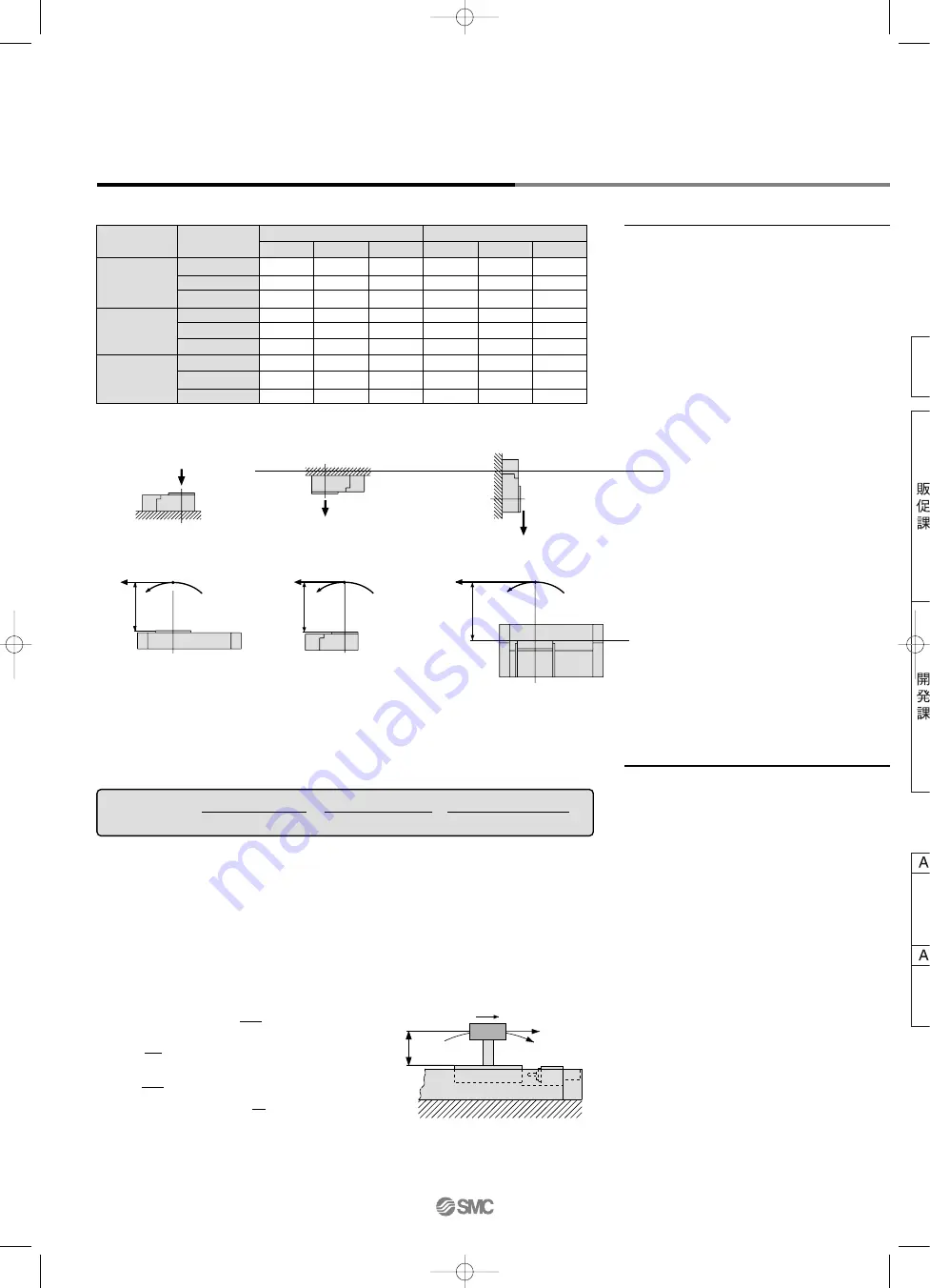
Maximum Allowable Moment/Maximum Load Mass
Model
MY2H
MY2C
MY2HT
Bore size
(mm)
16
25
40
16
25
40
16
25
40
Maximum allowable moment (N
⋅
m)
M
1
5
13
45
7
28
60
46
100
200
M
2
4
14
33
6
26
50
55
120
220
M
3
3.5
10
28
7
26
60
46
100
200
Maximum load mass (kg)
m
1
18
35
68
15
32
62
20
38
80
m
2
16
35
66
13
30
62
18
35
80
m
3
14
30
57
13
30
62
18
35
80
Maximum Allowable Moment
Select the moment from within the range of
operating limits shown in the graphs. Note
that the maximum load mass value may
sometimes be exceeded even within the
operating limits shown in the graphs.
Therefore, also check the allowable load for
the selected conditions.
Maximum Load Mass
Select the load mass from within the range
of limits shown in the graphs. Note that the
maximum allowable moment value may
sometimes be exceeded even within the
operating limits shown in the graphs.
Therefore, also check the allowable
moment for the selected conditions.
Moment (N
⋅
m)
Load mass (kg)
<
Calculation of guide load factor>
M
1
= F
1
x L
1
F
1
L
1
F
2
L
2
M
2
= F
2
x L
2
m
2
L
3
M
3
= F
3
x L
3
F
3
m
3
m
1
F
E
M
E
υ
m
L
1
The above values are the maximum allowable values for moment and load. Refer to each graph regarding the maximum
allowable moment and maximum load mass for a particular piston speed.
1. Maximum load mass (1), static moment (2), and dynamic moment (3) (at the time of impact with
stopper) must be examined for the selection calculations.
∗
To evaluate, use
υ
a (average speed) for (1) and (2), and
υ
(impact speed
υ
= 1.4
υ
a) for (3).
Calculate m max for (1) from the maximum load mass graph (m
1
, m
2
, m
3
) and Mmax for (2) and (3) from the maximum
allowable moment graph (M
1
, M
2
, M
3
).
Sum of guide
load factors
Σ
α =
Load mass
[
m
]
Maximum load mass
[
m max]
Static moment
[
M]
(1)
Allowable static moment
[
Mmax]
Dynamic moment
[
M
E
]
(2)
Allowable dynamic moment
[
M
E
max]
Note 1) Moment caused by the load, etc., with cylinder in resting condition.
Note 2) Moment caused by the impact load equivalent at the stroke end (at the time of impact with stopper).
Note 3) Depending on the shape of the workpiece, multiple moments may occur. When this happens, the sum of the load
factors (
Σ
α
) is the total of all such moments.
2. Reference formulas [Dynamic moment at impact]
Use the following formulas to calculate dynamic moment when taking stopper impact into consideration.
m
F
F
E
υ
a
M
1.4
υ
=
1.4
υ
a (mm/s) F
E
=
υ
a
⋅
g
⋅
m
Note 4)
100
1
∴
M
E
=
⋅
F
E
⋅
L
1
= 0.05
υ
a m L
1
(N
⋅
m)
Note 5)
3
Note 4)
υ
a
is a dimensionless coefficient for calculating impact force.
Note 5) Average load coefficient (= ):
This coefficient is for averaging the maximum load moment at
the time of stopper impact according to service life calculations.
3. Refer to pages 1096 and 1097 for detailed selection procedures.
υ
L
1
M
E
g
: Impact speed (mm/s)
: Distance to the load’s center of gravity (m)
: Dynamic moment (N
⋅
m)
: Gravitational acceleration (9.8 m/s
2
)
: Load mass (kg)
: Load (N)
: Load equivalent to impact (at impact with stopper) (N)
: Average speed (mm/s)
: Static moment (N
⋅
m)
1.4
100
1
3
+
+
1
1090
Series
MY2
P1057-P1120-E.qxd 08.10.3 2:27 PM Page 1090
Courtesy of Steven Engineering, Inc.-230 Ryan Way, South San Francisco, CA 94080-6370-Main Office: (650) 588-9200-Outside Local Area: (800) 258-9200-www.stevenengineering.com