


MWB#-TF2Z418EN
Page 2 of 3
Avoid:
Load centre of gravity and cylinder shaft centre are not matched; however, can be used
if all of the generated moment is absorbed by an effective guide.
Prefer:
Load centre of gravity and cylinder shaft centre are matched
Do not scratch or dent the sliding parts of the piston rod.
Damage to the seals may lead to air leakage and locking failure.
Do not apply loads with impact, strong vibration or rotational
force while the lock mechanism is activated.
External impact load, strong vibration or rotating force may break or
reduce the life of lock part.
Prevent seizure of the rotating parts of mounting bracket.
Prevent the seizure of rotating parts (pins, etc.) of mounting brackets
by applying grease.
Do not use the product until you have verified that the equipment
can operate properly.
After installation, apply compressed air and power supplies to the
equipment and perform appropriate functional and leakage inspections
to make sure the equipment is mounted properly.
There is a vent hole on the element. If the ventilation is not
adequate, there will be locking/unlocking delay or operation
failure. Install the cylinder so that the element is not covered.
Keep sufficient distance (10mm or more recommended) away
from the wall.
Lock unit element
3.5 Additional mounting precautions for Lock Unit
1. Ensure that the sliding surface of the rod to be inserted into the
lock unit is not scratched or dented during the mounting or
adjustment of this product.
Scratches or dents on the surface of the rod may cause unusual wear
on the inner surface of the brake pad or decrease its holding force.•
Chamfer the rod end to be inserted into the lock unit as shown in the
figures below to prevent the seal and inner periphery of the lock unit
from being scratched.
3.6 Provisional rod
The provisional rod is used to keep the alignment of the interior
structure stable during delivery. Remove the provisional rod
immediately before mounting into the application. Before this, the
locking unit must be released by compressed air.
3.7 Selection
Warning
1. When in the locked state, do not apply a load accompanied by an
impact shock, strong vibration or turning force, etc.
Use caution, because an external action such as an impacting load,
strong vibration or turning force, may damage the locking mechanism or
reduce its life.
2. Consider stopping accuracy and the amount of overrun when an
intermediate stop is performed
.
Due to the nature of a mechanical lock, there is a momentary lag with
respect to the stop signal, and a time delay occurs before stopping. The
cylinder stroke resulting from this delay is the overrun amount. The
difference between the maximum and minimum overrun amounts is the
stopping accuracy.
Place a limit switch before the desired stopping position, at a distance
equal to the overrun amount.
The limit switch must have a detection length (dog length) of the
overrun
.
SMC’s auto switches have operating ranges from 8 to 14 mm
(depending on the auto switch model). When the overrun amount
exceeds this range, self-holding of the contact should be performed at
the auto switch load side.
For the stopping accuracy, refer to 2.3 Stopping Accuracy.
3. In order to further improve stopping accuracy, the time from the
stop signal to the operation of the lock should be shortened as
much as possible.
To accomplish this, use a device such as a highly responsive electric
control circuit or solenoid valve, and place the solenoid valve as close as
possible to the cylinder.
4. Note that the stopping accuracy will be influenced by changes in
piston speed.
When piston speed changes during the course of the cylinder stroke due
to variations in the load or disturbances, etc., the dispersion of stopping
positions will increase. Therefore, consideration should be given to
establishing a standard speed for the piston just before it reaches the
stopping position. Moreover, the dispersion of stopping positions will
increase during the cushioned portion of the stroke and during the
accelerating portion of the stroke after the start of operation, due to the
large changes in piston speed.
5. The holding force (max. static load) indicates the maximum
capability to hold a static load without loads, vibration and impact.
This does not indicate a load that can be held in ordinary conditions.
Select the most suitable bore sizes for the operating conditions in
accordance with the selection procedures explained in MWB catalogue
or operation manual. The Model Selection in the catalogue or operation
manual is based on use at the intermediate stop (including emergency
stop during operation). However, when the cylinder is in a locked state,
kinetic energy does not act upon it. Under these conditions, use the load
mass at the maximum speed (V) of 100 mm/s shown in graphs 5 to 7 on
page 6 of the catalogue depending on the operating pressure and select
models.
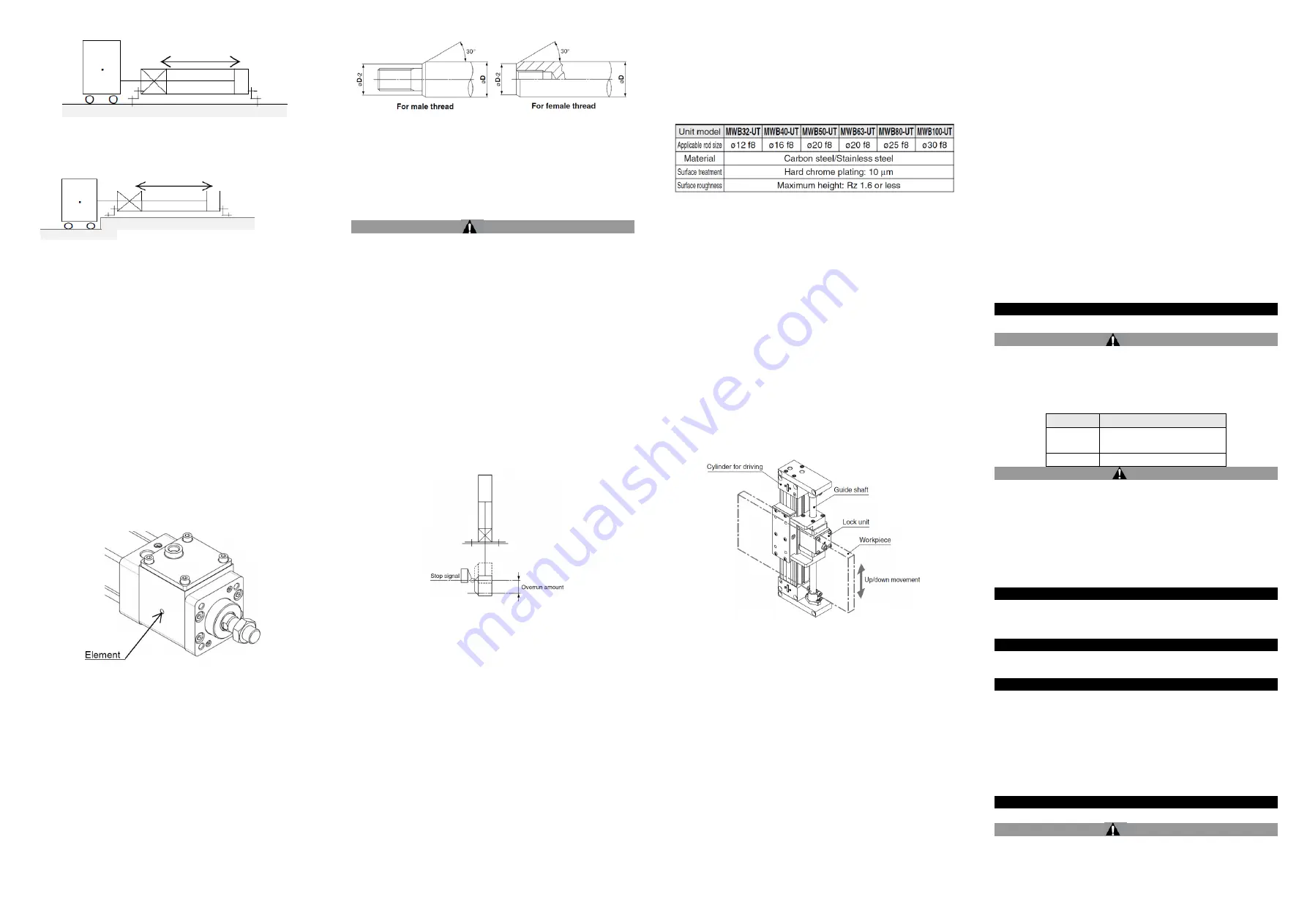
3.8 Additional selection precautions (Lock unit specific)
• Use a rod of the size recommended in the following table.
Using any rod other than the rods recommended above may cause
damage to internal parts of the lock unit, faulty mounting of the lock unit,
operation failure, decrease in holding force, etc.
1. The lock unit may be damaged if an excessive lateral load or external
force is applied to it. Fully consider this point.
2. Do not use the lock unit for any application where the rod rotates.
3. When in the locked state, do not apply a load accompanied by an
impact shock, strong vibration, turning force, etc.
Note that an external action, such as an impacting load, strong
vibration, or turning force, may damage the lock unit or reduce its life.
4. Excessively long piping between the unlock port of the lock unit and
the solenoid valve for the lock, or a pipe that is too small may affect the
stopping accuracy of the lock unit.
5. When unlocking is performed from the locked state with some thrust
or load still applied to the lock unit, cylinder lurching may occur. In
addition, frequent occurrence of excessive cylinder lurching or a similar
problem due to the load being applied will damage the lock unit or
reduce its life. Take appropriate measures for the circuit and/or the
system. When using the lock unit in combination with a pneumatic
cylinder, cylinder lurching can be prevented by using a balance circuit,
such as the recommended pneumatic circuits on catalogue page 41.
6. When using the lock unit by placing it in parallel with the cylinder for
driving as shown in the figure below, align the cylinder with the rod.
3.9 Pneumatic Circuit
1. Be certain to use a pneumatic circuit which will apply balancing
pressure to both sides of the piston when in a locked stop.
In order to prevent cylinder lurching after a lock stop, when restarting or
when pneumatically unlocking, a circuit should be used to which will
apply balancing pressure to both sides of the piston, thereby cancelling
the force generated by the load in the direction of piston movement.
2. The effective area of the unlocking solenoid valve should be at
least 50% of the effective area of the cylinder driving solenoid
valve, and it should be installed as close to the cylinder as
possible so that it is closer than the cylinder driving solenoid
valve.
If the effective area of the unlocking solenoid valve is small or if it is
installed at a distance from the cylinder, the time required for
exhausting air for unlocking will be longer, which may cause a delay in
the locking operation.
The delay in the locking operation may result in problems such as
increase of overrunning when performing intermediate stop or
emergency stop during operation, or if maintaining position from the
operation stop state such as drop prevention, workpieces may be
dropped depending on the timing of the load action to the operation
delay of the lock.
3. Avoid backflow of the exhaust pressure when there is a
possibility of interference of exhaust air, for example for a
common exhaust type valve manifold
.
The lock may not operate properly when the exhaust air pressure
backflows due to interference of the exhaust air when exhausting air for
lock release. It is recommended to use an individual exhaust type
manifold or individual valves.
4. Allow at least 0.5 seconds from a locked stop (intermediate stop
of the cylinder) until release of the lock
.
When the locked stop time is too short, the piston rod (and load) may
lurch at a speed greater than the control speed of the speed controller.
5. When restarting, control the switching signal for the unlocking
solenoid valve so that it acts before or at the same time as the
cylinder drive solenoid valve.
If the signal is delayed, the piston rod (and load) may lurch at a speed
greater than the control speed of the speed controller.
6. Carefully check for dew condensation due to repeated air supply
and exhaust of the locking solenoid valve.
The operating stroke of the lock part is very small. So, if the piping is
long and the air supply and exhaust are repeated, the dew
condensation caused by the adiabatic expansion accumulates in the
lock part. This may corrode internal parts, causing air leak or lock
release fault.
4 Settings
4.1 Adjustment
Warning
Do not open the cushion valve beyond the stopper.
As a retaining mechanism for the cushion valve, a crimped section
(ø32) or retaining ring (ø40 to ø100) is installed, and the cushion valve
should not be opened beyond that point. If not operated in accordance
with the above precautions, the cushion valve may be ejected from the
cover when air pressure is supplied.
Bore size [mm] Hexagon wrench size of cushion valve
32, 40
2.5
50, 63
3
80, 100
4
Caution
Adjust the cylinder’s air balance.
Balance the load by adjusting the air pressure in the rod and head sides
of the cylinder with the load connected to the cylinder and the lock
released. Lurching of the cylinder when unlocked can be prevented by
carefully adjusting this air balance.
Adjust the mounting positions of the detectors on auto switches,
etc.
When intermediate stops are to be performed, adjust the mounting
positions of detectors on auto switches, etc., taking into consideration
the overrun amount with respect to the desired stopping positions.
5 How to Order
Refer to customer drawing for
‘How to Order’.
Applicable Auto Switches -
Refer to MWB catalogue.
6 Outline Dimensions (mm)
Refer to MWB-X3075, MWB-X3246 and MWB-UT-X3075 drawing for
dimensions.
7 Internal Construction
Refer to MWB Catalogue for internal construction drawing.
8 Maintenance
8.1 General Maintenance
Caution
Do not disassemble the locking section. Replace the whole locking
unit. If repair is necessary, contact your nearest SMC sales branch.
Consumable parts of the cylinder are replaceable. Use standard
MWB seal kit as shown below;


