


LEF-TFN01
3 Specifications
LEFS series - Ball screw drive
Note 1) The strokes shown in ( ) are produced upon receipt of order.
Note 2) The speed is dependent on the workload. Check the “Speed-workload
graphs” for the selected model in the catalogue or the operation manual.
Note 3) Impact resistance:
No malfunction occurred when the actuator was tested with a drop tester in
both an axial direction and perpendicular direction to the lead screw.
(The test was performed with the actuator in the initial state.)
Vibration resistance:
No malfunction occurred in a test ranging between 45 to 2000 Hz, when the
actuator was tested in both an axial direction and a perpendicular direction to
the lead screw. (The test was performed with the actuator in the initial state.)
Note 4) The "Power consumption" (including the controller) is for when the actuator is
operating.
Note 5) The “Standby power consumption when operating” (including the controller) is
for when the actuator is stopped in the set position during operation.
Note 6) The "Momentary max. power consumption" (including the controller) is for
when the actuator is operating.
This value can be used for the selection of the power supply.
Note 7) Only applies to actuators supplied with a lock.
Note 8) For the actuator with lock, please add the power consumption for the lock.
LEFB series - Belt drive
3 Specification (continued)
Note 1) The strokes shown in ( ) are produced upon receipt of order.
Note 2) The speed is dependent on the workload.
Check the “Speed-workload graph” for the selected model in the catalogue
or operation manual.
Note 3) Impact resistance:
No malfunction occurred in a test ranging between 45 to 2000 Hz, when the
actuator was tested in both an axial direction and a perpendicular direction to
the lead screw. (The test was performed with the actuator in the initial state.)
Vibration resistance:
No malfunction occurred in a test ranging between 45 to 2000 Hz. Test was
performed in both an axial direction and a perpendicular direction to the drive
belt. (The test was performed with the actuator in the initial state.)
Note 4) The "Power consumption" (including the controller) is for when the actuator is
operating.
Note 5) The “Standby power consumption when operating” (including the controller) is
for when the actuator is stopped in the set position during operation.
Note 6) The "Momentary max. power consumption" (including the controller) is for
when the actuator is operating.
This value can be used for the selection of the power supply.
Note 7) Only applies to actuators supplied with a lock.
Note 8) For the actuator with lock, please add the power consumption for the lock.
4 Installation
4.1 Design and selection
Warning
•
Do not apply a load in excess of the actuator specification.
A product should be selected based on the maximum work load and
allowable moment.
If the product is used outside of the operating specification, the eccentric
load applied to the guide will become excessive and have adverse
effects such as creating play in the guide, reduced accuracy and
reduced product life.
•
Do not exceed the speed limit of the actuator specification.
Select a suitable actuator by the relationship of allowable work load
and speed.
Noise or reduction of accuracy may occur if the actuator is operated in
excess of its specification and could lead to reduced accuracy and
reduced product life.
•
Do not use the product in applications where excessive external
force or impact force is applied to it.
This can lead to premature failure of the product.
Caution
•
Do not operate by fixing the table and moving the actuator body.
An excessive load will be applied to the table, which could lead to
damage to the actuator and reduced accuracy and reduced product life.
•
Belt drive actuator cannot be used for vertically mounted
applications.
•
••
•
In the case of the belt driven actuator, vibration may occur during
operation at speeds within the actuator specification, this could be
caused by the operating conditions. Change the speed setting to a
speed that does not cause vibration.
4 Installation (continued)
4.2 Mounting
Caution
•
Keep the flatness of mounting surface to within 0.1 mm or less.
Insufficient flatness of the work piece or the surface onto which the
actuator body is to be mounted can cause play in the guide and
increased sliding resistance.
•
When mounting the workpiece or other device to the actuator
tighten the fixing screws with adequate torque within the specified
torque range.
Tightening the screws with a higher torque than the maximum may
cause malfunction, whilst tightening with a lower torque can cause the
displacement of the mounting position or in extreme conditions
detaching of the work piece.
Use screws with adequate length, but with length less than the
maximum thread depth.
The use of screws that are to long can touch the body and cause
malfunction.
•
When mounting the actuator, use screws with adequate length and
tighten them with adequate torque and use all of the mounting
holes to maintain the catalogue performance.
Tightening the screws with a higher torque than recommended may
cause malfunction, whilst the tightening with lower torque can cause the
displacement of mounting position or in extreme conditions the actuator
could become detached from its mounting position.
•
When mounting the actuator, leave a gap of 40 mm or more to allow
for bending of the actuator cable.
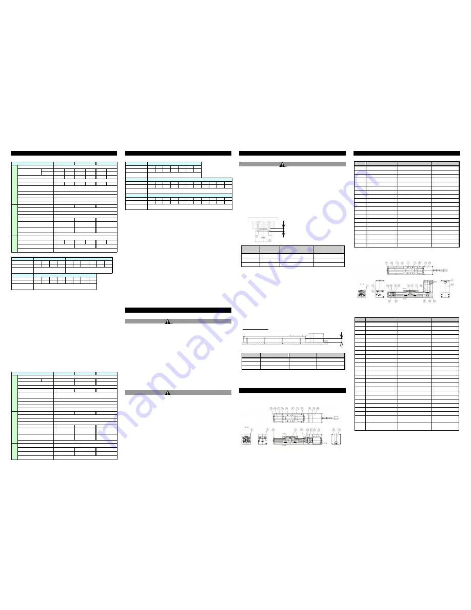
5 Names and Functions of Individual Parts
LEFS series – Ball screw drive
(See LEFS parts list in next column)
5 Names and Functions of Individual Parts (continued)
Parts list for LEFS
No.
Part
Material
Remarks
1
Body
Aluminium alloy
Anodized
2
Rail guide
-
3
Ball screw Ass’y
-
4
Connector shaft
Stainless steel
5
Table
Aluminium alloy
Anodized
6
Blanking plate
Aluminium alloy
Anodized
7
Seal band holder
Synthetic resin
8
Housing A
Aluminium die-cast
Chromating
9
Housing B
Aluminium alloy
Anodized
10
Bearing holder
Aluminium alloy
11
Motor mount
Aluminium alloy
Anodized
12
Coupling
-
13
Motor cover
Aluminium alloy
Anodized
14
End cover
Aluminium alloy
Anodized
15
Motor
-
16
Rubber bushing
NBR
17
Band holder
Stainless steel
18
Dust seal band
Stainless steel
19
Bearing
-
20
Bearing
-
LEFB series – Belt drive
Parts list for LEFB
ℓ
Work piece mounting
ℓ
Actuator mounting
Model
Bolt size
φA
(
mm)
ℓ
(
mm
)
LEF*16
M3
3.4
20
LEF*25
M4
4.3
24
LEF*32
M5
5.5
30
Model
Bolt size
Maximum tightening
torque (N•m)
ℓ (Maximum thread
depth (mm])
LEF*16
M4 x 0.7
2.1
6
LEF*25
M5 x 0.8
5.7
8
LEF*32
M6 x 1
7.4
9
No.
Part
Material
Remarks
1
Body
Aluminium alloy
Anodized
2
Rail guide
-
3
Belt
-
4
Belt holder A
Carbon steel
Chromating
5
Belt holder B
Aluminium alloy
Anodized
6
Table
Aluminium alloy
Anodized
7
Blanking plate
Aluminium alloy
Anodized
8
Seal band holder
Synthetic resin
9
Housing A
Aluminum die-cast
Chromating
10
Pulley holder
Aluminium alloy
11
Pulley shaft
Stainless steel
12
End pulley
Aluminium alloy
Anodized
13
Motor pulley
Aluminium alloy
Anodized
14
Motor mount
Aluminium alloy
Anodized
15
Motor cover
Aluminium alloy
Anodized
16
End cover
Aluminium alloy
Anodized
17
Band holder
Stainless steel
18
Motor
-
19
Rubber bushing
NBR
20
Stopper
Aluminium alloy
21
Dust seal band
Stainless steel
22
Bearing
-
23
Bearing
-
24
Tension
adjustment bolt
Chromium
molybdenum steel
Nickel plating
25
Pulley
holding bolt
Chromium
molybdenum steel
Nickel plating
Weight
Model
Stroke (mm)
Note1)
100
200
300
(400)
100
200
300
(400)
500
(600)
Weight (kg)
0.90
1.05
1.20
1.35
1.84
2.12
2.40
2.68
2.96
3.24
Additional weight
for lock (kg)
Model
Stroke (mm)
Note1)
100
200
300
(400)
500
(600)
(700)
(800)
Weight (kg)
3.35
3.75
4.15
4.55
4.95
5.35
5.75
6.15
Additional weight
for lock (kg)
LEFS16
LEFS25
0.12
0.19
LEFS32
0.35
Horizontal
9
10
20
20
40
45
Vertical
2
4
7.5
15
10
20
10 - 500
5 - 250
12 - 500
6 - 250
16 - 500
8 - 250
10
5
12
6
16
8
20
39
78
157
108
216
See the "Weight" table below for the applicable strokes.
123
0.15 (Screw mounting type), 0.17 (DIN rail mounting type)
51
57
LEFS 16
LEFS 25
LEFS 32
18
16
44
± 0.02
Ball screw
Linear guide
50 / 20
5 to 40
(No condensation or freezing)
35 to 85 (No condensation or freezing)
E
le
c
tr
ic
s
p
e
c
if
ic
a
ti
o
n
□28
□42
□56.4
Step motor (Servo 24VDC)
Incremental A/B phase (800 pulse/rotation)
24 ±10%
22
38
50
L
o
c
k
s
p
e
c
if
ic
a
ti
o
n
No excitation operating type
3.6
5
5
24 ±10%
Holding force (N)
Power consumption (W)
Note8)
Rated voltage (VDC)
Stroke (mm)
Speed (mm/s)
Note2)
Work load (kg)
Note2)
Drive method
Guide type
Operating temperature range (
℃
)
Operating humidity range (%)
Motor size
Type of Motor
Model
Positioning repeatability (mm)
Lead (mm)
Impact resistance/vibration
resistance (m/s
2
)
Note3)
A
c
tu
a
to
r
s
p
e
c
if
ic
a
ti
o
n
Encoder
Rated voltage (VDC)
Power consumption (W)
Note4)
Standby power consumption when
operating (W)
Note5)
Momentary max. power
consumption (W)
Note6)
Controller weight (kg)
Type
Note7)
Work load (kg)
Note2)
Horizontal
See the "Weight" table below for the applicable strokes.
Incremental A/B phase (800 pulse/rotation)
24 ±10%
44
No excitation operating type
51
60
24
32
52
0.15 (Screw mounting type), 0.17 (DIN rail mounting type)
24 ±10%
4
3.6
19
5
36
48 - 1500
± 0.1
L
o
c
k
s
p
e
c
if
ic
a
ti
o
n
Linear guide
E
le
c
tr
ic
s
p
e
c
if
ic
a
ti
o
n
□28
5
127
18
16
□42
□
56.4
48
48
48
5 to 40
(No condensation or freezing)
14
Step motor (Servo 24VDC)
1
48 - 1100
5
48 - 1400
35 to 85 (No condensation or freezing)
Belt
Drive method
Guide type
50 / 20
LEFB 32
Stroke (mm)
Model
LEFB 16
LEFB 25
A
c
tu
a
to
r
s
p
e
c
if
ic
a
ti
o
n
Positioning repeatability (mm)
Lead equivalent (mm)
Impact resistance/vibration
resistance (m/s
2
)
Note3)
Speed (mm/s)
Note2)
Operating temperature range (
℃
)
Operating humidity range (%)
Motor size
Type of Motor
Encoder
Rated voltage (VDC)
Power consumption (W)
Note4)
Standby power consumption when
operating (W)
Note5)
Power consumption (W)
Note8)
Rated voltage (VDC)
Momentary max. power
consumption (W)
Note6)
Controller weight (kg)
Type
Note7)
Holding force (N)
Weight
Model
Stroke (mm)
Note1)
(300)
500
(600)
(700)
800
(900)
1000
Weight (kg)
1.19
1.45
1.58
1.71
1.84
1.97
2.10
Additional weight
for lock (kg)
Model
Stroke (mm)
Note1)
(300)
500
(600)
(700)
800
(900)
1000 (1200) (1500) (1800) (2000)
Weight (kg)
2.39
2.85
3.08
3.31
3.54
3.77
4.00
4.46
5.15
5.84
6.30
Additional weight
for lock (kg)
M odel
Stroke (mm)
Note1)
(300)
500
(600)
(700)
800
(900)
1000 (1200) (1500) (1800) (2000)
Weight (kg)
4.12
4.8
5.14
5.48
5.82
6.16
6.5
7.18
8.2
9.22
9.9
Additional weight
for lock (kg)
0.35
LEFB32
LEFB25
0.12
0.19
LEFB16


