background image


PRODUCT NAME


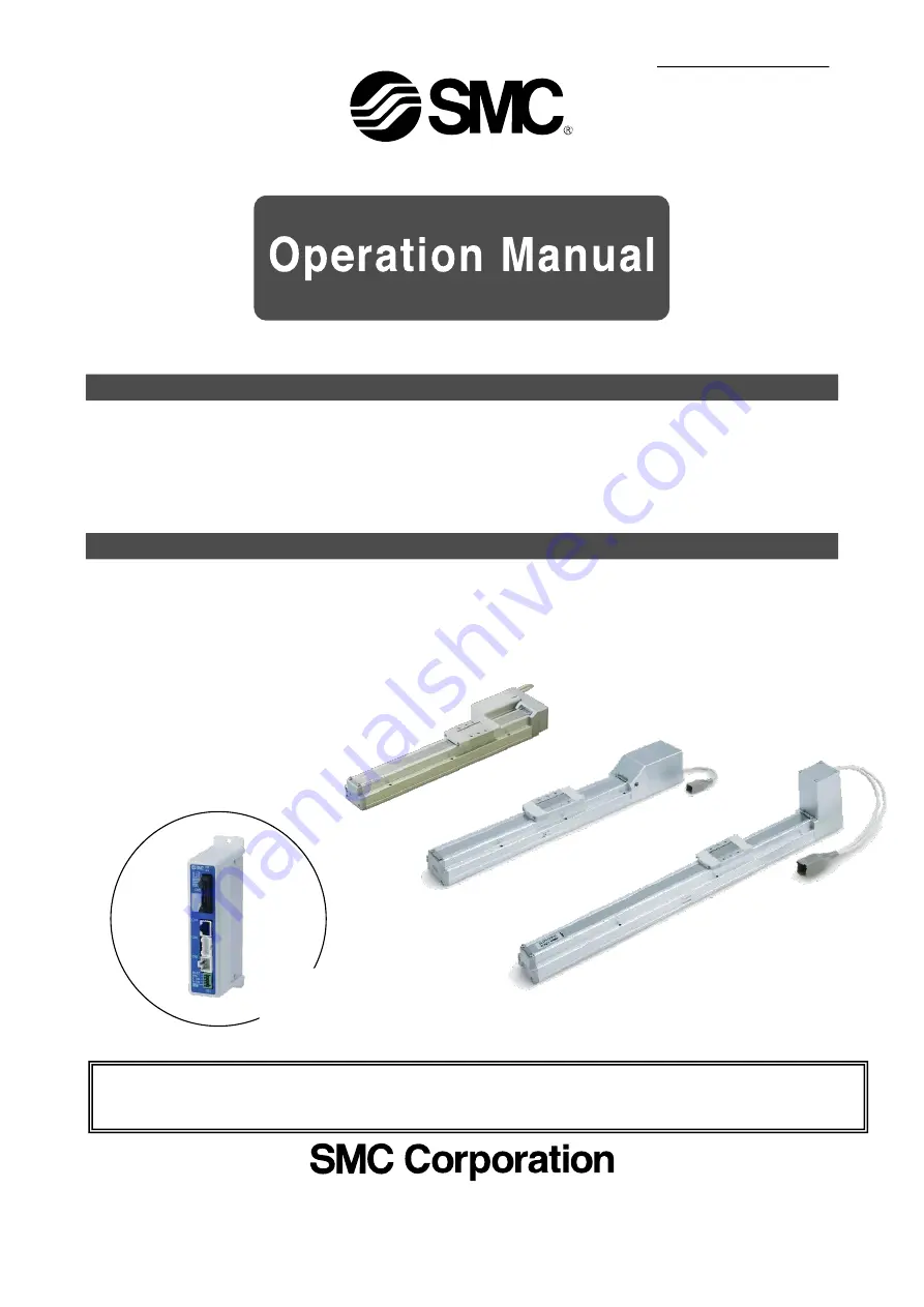
Electric Actuator 

Slider Type 

Step motor

Servo motor


MODEL / Series


LEF Series 

Applicable models: LEFS, LEFB


Doc. no. LEF-OM00213 


This manual describes the actuators operation in combination with the LEC*6


series controllers. 

Refer to the manual relevant to the controller being used for full


operating instructions. 

<Controller> 

LEC Series


2021-05-20 10:32

DW913599

Summary of Contents for LEC Series

Page 1: ... Series LEF Series Applicable models LEFS LEFB Doc no LEF OM00213 This manual describes the actuators operation in combination with the LEC 6 series controllers Refer to the manual relevant to the controller being used for full operating instructions Controller LEC Series ...

Page 2: ...struction 21 3 2 Setting Function 22 3 3 Step data setting method 25 3 4 Parameter setting method 31 4 Wiring of cables Common precautions 34 5 Electric actuators Common precautions 35 5 1 Design and selection 35 5 2 Mounting 36 5 3 Handling 36 5 4 Operating environment 37 5 5 Maintenance 38 5 6 Precautions for actuator with lock 38 6 Electric actuators Slider type Common precautions 39 6 1 Design...

Page 3: ...uld also continuously review all specifications of the product referring to its latest catalog information with a view to giving due consideration to any possibility of equipment failure when configuring the equipment 2 Only personnel with appropriate training should operate machinery and equipment The product specified here may become unsafe if handled incorrectly The assembly operation and maint...

Page 4: ...r replacement parts Please consult your nearest sales branch For any failure or damage reported within the warranty period which is clearly our responsibility a replacement product or necessary parts will be provided This limited warranty applies only to our product independently and not to any other damage incurred due to the failure of the product Prior to using SMC products please read and unde...

Page 5: ...aching box 1 7 Controller setting kit The controller setting software The communication cable USB cable and conversion unit are included 1 Part name Conditions Power supply 24VDC Do not use the power supply with Inruch restraining type Refer to power consumption of each actuator See 2 1Specification on p 9 Prepare the power supply that has capacity of Moment max power consumption or more Wire AWG2...

Page 6: ...ive a Driving preparation Servo On Return to ORIG Select Monitor Select OK 1 SVRE lighting is confirmed b JOG Drive 2 Select Return to ORIG Clicking arrow button Operation c Driving stop Servo Off Select Test Select OK Select test Caution If an alarm is generated 1 When ALARM is generated release it by selecting 2 Reset In the case of an alarm code that cannot be released with Reset turn the power...

Page 7: ... the ACT Controller setting software Step data No Move M Speed Position Pushing F TriggLV In pos mm s mm mm 0 Absolute 250 30 00 0 0 0 50 Step data No Move M Speed Position Pushing F TriggLV In pos mm s mm mm 0 Absolute 250 50 00 0 0 0 50 Procedure 1 Select Step No 0 You can select anywhere in the row Procedure 2 Select Drive Procedure 3 Select Step No 1 You can select anywhere in the row Procedur...

Page 8: ...t Press the 3 SET key JOG 1 RTN ORIG Done JOG Move Posn 123 45mm Operates by 2 JOG key JOG End side JOG Motor side Press the 5 MENU key Check 1 EXT Inp ON OK Press the 3 SET key 1 Drive test Press the 4 Down key Test 1 Step No 0 Test Start Posn 50 00mm Press the 3 SET key Step No 0 move Test Complete 2 Select Step No Press the 4 Up key Test 1 Step No 1 Test Start Posn 0 00mm Press the 1 Number key...

Page 9: ...etween operation procedure and input output signals refer to section 3 3 Step Data setting method p 23 to 26 アラーム ALARM ジョグ JOG 設定 SETTING テスト TEST モニタ MONITOR データ DATA The power supply is turned on Screen showing the actuator stop at position of 50mm Step No 0 Step 1 Step No 0 Posn 50 00mm Speed 250mm s Press the 4 Down key Select Posn Change of positioning stop position Posn 50 mm 30mm Step 1 St...

Page 10: ... 95 5 15 5 35 5 55 5 75 5 95 6 15 6 35 6 55 6 75 6 95 Additional weight for lock kg LEFS16 0 12 LEFS25 0 26 LEFS32 0 53 14 15 12 25 30 20 45 50 9 10 10 20 20 15 40 45 2 4 0 5 7 5 15 4 10 20 500 10 to 700 5 to 360 20 to 1100 12 to 750 6 to 400 24 to 1200 16 to 800 8 to 520 501 600 20 to 900 12 to 540 6 to 270 24 to 1200 16 to 800 8 to 400 601 700 20 to 630 12 to 420 6 to 230 24 to 930 16 to 620 8 t...

Page 11: ...2 0 100 200 300 400 500 600 速度 V mm s 水平搬送質量 W kg Bリード Aリード 0 5 10 15 20 0 200 400 600 800 1000 1200 速度 V mm s 水平搬送質量 W kg Bリード Aリード Hリード 0 10 20 30 40 50 0 200 400 600 800 1000 1200 速度 V mm s 水平搬送質量 W kg Bリード Aリード Hリード 0 2 4 6 8 10 12 0 100 200 300 400 500 600 速度 V mm s 垂直搬送質量 W kg Bリード Aリード 0 5 10 15 20 0 100 200 300 400 500 600 速度 V mm s 垂直搬送質量 W kg Bリード Aリード Hリード 0 10 20 30 40 50 0 100 200 300...

Page 12: ...er type LECP6 LECP1 LECPMJ JXC91 Note2 Speed mm s Stroke range 30 to 660 30 to 570 20 to 440 20 to 380 24 VDC 10 5 225 113 75 Step motor Servo 24V DC Non magnetizing lock 56 4 141 43 100 5 to 40 Linear Guide Ball screw LEFS40 Ball screw Belt LEFS40L R 50 20 2 20 0 05 or less 0 1 or less 0 015 Lead H 0 02 0 02 3 000 10 to 220 10 to 250 23 60 2 50 10 to 300 10 to 300 10 to 300 10 to 300 10 to 250 30...

Page 13: ...s supplied with a lock Horizontal 7 10 5 11 18 Vertical 2 4 1 2 5 5 500 1 to 500 1 to 250 2 to 800 2 to 500 1 to 250 501 600 2 to 800 2 to 500 1 to 250 601 700 2 to 630 2 to 420 1 to 230 701 800 2 to 550 2 to 330 1 to 180 Basic type High precision type Basic type High precision type 10 5 20 12 6 20 39 47 78 157 Stroke range Note2 Speed mm s LEFS25A Work load kg note2 Max acceleration deceleration ...

Page 14: ... 100 150 200 250 300 350 400 450 500 550 600 650 700 750 800 Weight kg 1 70 1 84 1 98 2 12 2 26 2 40 2 54 2 68 2 82 2 96 3 10 3 24 3 38 3 52 3 66 3 80 Additional w eight for lock kg LEFS16A 0 12 LEFS25A 0 26 0 2 4 6 8 10 12 0 100 200 300 400 500 600 700 800 900 速度 V mm s 水平搬送質量 W kg Bリード Aリード 0 5 10 15 20 0 200 400 600 800 1000 1200 速度 V mm s 水平搬送質量 W kg Bリード Aリード Hリード 0 2 4 6 8 10 12 0 100 200 30...

Page 15: ...1000 300 500 600 700 800 900 1000 1200 1500 1800 2000 Weight kg 1 19 1 45 1 58 1 71 1 84 1 97 2 10 2 39 2 85 3 08 3 31 3 54 3 77 4 00 4 46 5 15 5 84 6 30 Additional weight for lock kg 0 12 0 26 Model LEFB32 Stroke mm 300 500 600 700 800 900 1000 1200 1500 1800 2000 Weight kg 4 12 4 80 5 14 5 48 5 82 6 16 6 50 7 18 8 20 9 22 9 90 Additional weight for lock kg 0 53 Speed Workload graph Horizontal Tr...

Page 16: ...Note 9 For the actuator with lock please add the power consumption for the lock Weight Model LEFB16A LEFB25A Stroke mm 300 500 600 700 800 900 1000 300 500 600 700 800 900 1000 1200 1500 1800 2000 Weight kg 1 19 1 45 1 58 1 71 1 84 1 97 2 10 2 39 2 85 3 08 3 31 3 54 3 77 4 00 4 46 5 15 5 84 6 30 Additional weight for lock kg 0 12 0 19 Speed Workload graph Horizontal Transfer Horizontal 78 Lock uni...

Page 17: ...s purchased separately confirm that the combination of the controller which you have and the actuator is compatible P 34 Notes 5 3 Caution 1 Be sure to check the following before use 1 Check that actuator label for model number This matches the controller 2 Check Parallel I O configuration matches NPN or PNP 1 2 LEFS16A 100 NPN ...

Page 18: ... separately confirm that the combination of the controller which you have and the actuator is compatible P 34 Notes 5 3 Caution 1 Be sure to check the following before use 1 Check that actuator label for model number This matches the controller 2 Check Parallel I O configuration matches NPN or PNP 1 2 LEFS16A 100 NPN ...

Page 19: ...band holder Synthetic resin 8 Housing A Aluminum die casted Coating 9 Housing B Aluminum die casted Coating 10 Bearing stopper Aluminum alloy 11 Motor mount Aluminum alloy 12 Coupling A A A A B B No Description Material Note 13 Motor cover Aluminum alloy Anodized 14 End cover Aluminum alloy Anodized 15 Motor 16 Rubber bushing NBR 17 Band stopper Stainless steel 18 Dust seal band Stainless steel 19...

Page 20: ...ing A Aluminum die casted Coating 9 Housing B Aluminum die casted Coating 10 Bearing stopper Aluminum alloy 11 Return plate Aluminum alloy 12 Pulley Aluminum alloy 13 Pulley Aluminum alloy No Description Material Note 14 Belt 15 Cover plate Aluminum alloy Anodized 16 Table spacer Aluminum alloy LEFS32only 17 Motor 18 Motor cover Synthetic resin 19 Motor cover with lock Aluminum alloy 20 Band stopp...

Page 21: ...minum alloy 11 Pulley shaft Stainless steel 12 End pulley Aluminum alloy Anodized 13 Motor pulley Aluminum alloy Anodized 14 Motor mount Aluminum alloy Anodized No Description Material Note 15 Motor cover Aluminum alloy Anodized 16 End cover Aluminum alloy Anodized 17 Band stopper Stainless steel 18 Motor 19 Rubber bushing NBR 20 Stopper Aluminum alloy 21 Dust seal band Stainless steel 22 Bearing ...

Page 22: ...aybe fire risk and damage The actuator and controller are sold as a package If when only the actuator is purchased separately confirm that the combination of the controller which you have and the actuator is compatible See 5 3 Caution 1 on p 34 Be sure to check the following before use 1 Check that actuator label for model number This matches the controller 2 Check Parallel I O configuration match...

Page 23: ...ect function by the iconized menu at the first page Step data setting and monitoring at the second page Data Axis 1 Step No 0 Posn 123 45mm speed 400mm s It can be registered by SET after entering the values Operation status can be checked 1st screen 2nd screen Example of setting the step data Example of checking the operation status 1st screen Monitor Axis 1 Step No 1 Posn 12 34mm speed 50mm s Po...

Page 24: ...red JOG and fixed distance movement return to origin position test operation and testing of compulsory output can be done Controller setting soft ware Every function step data parameter monitor and teaching are indicated in a different window Teaching box The data in the controller can be saved forwarded in this teaching box Continuous test operation can be made after specifying five step data ...

Page 25: ...an be set ORIG ACC Acceleration when returning to origin can be set Test JOG It can make continuous operation at the set speed while the switch is being pressed MOVE It can make test operation at the set distance and speed from the current position when the switch is pressed Return to ORIG Test of return to origin can be done Test drive The operation of the specified step data can be tested Contin...

Page 26: ... 5 3 Caution 1 on P 34 Be sure to check the following before use 1 Check that actuator label for model number This matches the controller 2 Check Parallel I O configuration matches NPN or PNP Positioning operation In the positioning operation the actuator transfers to and stops at the target position The following image shows the set items and operation Confirmation of reaching the target position...

Page 27: ...peed For pushing operation only Not applicable for this product i Moving force Max Force at the positioning operation The force is automatically adjusted corresponding to the load Set 100 at step motor 250 at servo motor Not changeable j Area1 Area2 This is the condition that turns on the AREA output signal The setting condition should be Area 1 Area 2 It is possible to set at relative operation t...

Page 28: ...o Move M Speed Position Accel Decel Pushing F TriggLV Pushing Sp Moving F Area1 Area2 In pos mm s mm mm s2 mm s2 mm s mm mm mm 0 Absolute 100 100 00 3000 3000 0 0 0 100 80 00 90 00 0 50 INP Output signal 100 0 Speed mm s ON OFF Position mm c b In pos mm k 100 5 99 5 INP Output condition 0 10 20 30 40 50 60 70 80 90 100 Stroke mm The INP output signal is turned on from 100 mm 0 5 mm 99 5 mm Positio...

Page 29: ...thod Relative Condition 2 30mm position Step no 1 Step no 1 Move Method Relative Step data No Move M Speed Position Accel Decel Pushing F TriggLV Pushing Sp Moving F Area1 Area2 In pos mm s mm mm s2 mm s2 mm s mm mm mm 0 Relative 100 10 00 3000 3000 0 0 0 100 10 00 20 00 0 50 1 Relative 100 10 00 3000 3000 0 0 0 100 10 00 20 00 0 50 Attainment point 50 mm 0 10 20 30 40 50 Position 10 Relative C St...

Page 30: ...and the operation starts Complete 4 IN0 IN1 IN2 IN3 IN4 IN5 DRIVE note 3 5 OUT0 OUT1 OUT2 note 3 4 OUT3 OUT4 OUT5 After reaching of target position INP After stopping motion BUSY Step no 2 is selected and the operation starts Complete 5 SVON SVRE SETON note 2 INP Power to the motor is cut Note 1 means ON means OFF Note 2 The origin has been recognized when the operation is repeated so it can opera...

Page 31: ...he input signal Operation description 1 EMG Not energizing TB Stop switch Locking ESTOP SVRE SETON Powertothemotoriscutbythe Stop commandregardlessofwhetheritis operatingorstopping 2 EMG Energizing TB Stop switch Releasing ESTOP SVRE SETON Note 2 The stop is released Note 1 means ON means OFF and means negative logic Note 2 SETON signal does not change after releasing the STOP ...

Page 32: ...n offset is used for the return to origin See Origin offset on P 31 Description Extract Initial input value Input range Controller ID 1 1 to 64 note1 IO pattern 1 64 Acceleration deceleration pattern 1 Trapezoid motion S motion ratio 0 Stroke note 2 3 Stroke 2 10000 Stroke note 2 3 2 10000 Maximum speed Max speed of each product Step data input limit Max speed of each product Maximum acceleration ...

Page 33: ...ing Move to the opposite direction Origin Moving distance 2mm not changeable WARNING Do not alter any parameter except the ones shown Or else there is a possibility of damage 2 Method of changing direction of origin Use the following procedures when you change the direction of the origin Initial setting of origin is motor side Procedure 1 In the Parameter 01 dialogue box select the ORIG tab And th...

Page 34: ... Origin offset 0 Move in the opposite direction Moving distance 2mm Not changeable by the return to origin becomes origin 0 a In case of Origin direction CCW Example Actuator stroke 50mm Origin offset 0 Initial input value Changed to Origin offset 10 b In case of Origin direction CW Example Actuator stroke 50mm Origin offset 0 Initial input value Changed to Origin offset 10 Changed to Origin offse...

Page 35: ...harp angles where they enter the product 7 Avoid twisting folding rotating or applying an external force to the cable Risk of electric shock wire breakage contact failure and loss of control of the product can happen 8 Fix the motor cables protruding from the actuator in place before use The motor and lock cables are not robotic type cables and can be damaged when moved Therefore fix the cables an...

Page 36: ...rted after an emergency stop or abnormal stop of whole system Design the system so that human injury or equipment damage will not occur upon restart of operation of whole system 8 Never disassemble or modify including additional machining the product An injury ro failure can result It will cause the loss of the product performance 9 Do not use the stop signal EMG of the controller and stop switch ...

Page 37: ... body or reduce the speed so that the actuator does not vibrate 8 When attaching to the work piece do not apply strong impact or large moment If an external force over the allowable moment is applied it may cause looseness in the guide unit an increase in sliding resistance or other problems 9 Maintenance space Allow sufficient space for maintenance and inspection 10 When mounting the actuator or ...

Page 38: ... to the actuator 2 The ground should be exclusive use Less than 100Ω 3 The ground cable length should be as short as possible Unpackaging Caution 1 Check the received product is as ordered If the different product is installed from the one ordered injury or damage could result 5 4 Operating environment Warning 1 Avoid use in the following environments a Locations where a large amount of dusts and ...

Page 39: ...has been lubricated for life at manufacturer and does not require lubrication in service Contact SMC if lubrication will be applied 5 6 Precautions for actuator with lock Warning 1 Do not use the lock as a safety lock or a control that requires a locking force The lock used for the product with a lock is designed to prevent dropping of work piece 2 For vertical mounting use the product with a lock...

Page 40: ...n applications where excessive external force or impact force is applied to it This can lead to premature failure of the product 4 When the product repeatedly cycles with partial strokes see the table below operate it at a full stroke at least once every 10 strokes Otherwise lubrication can run out 5 Actuator sizing is necessary with the total workload including the external force if external forc...

Page 41: ...h a lower torque can cause the displacement of the mounting position or in extreme conditions detaching of the work piece Use screws with adequate length but with length less than the maximum thread depth The use of screws that are to long can touch the body and cause malfunction 3 When mounting the actuator use screws with adequate length and tighten them to the adequate torque And use all mounti...

Page 42: ...in fixed parts or fixing screws Items for belt check Check the belt regularly as shown in maintenance frequency Stop operation immediately and contact SMC when the belt appears to be like photographs shown below a Tooth shape canvas is worn out Canvas fiber becomes fuzzy Rubber is removed and the fiber becomes whitish Lines of fibers become unclear b Peeling off or wearing of the side of the belt ...

Page 43: ...of motor side of the Band holder and then remove the Dust seal band Re assembly The re assembly is completed by the reverse procedure of Dis assembly sections 1 2 and 3 Band holder Fixing bolts Refer to Re Assembly A Dust seal band End side Plate Seal band holder Refer to Re assembly B Dust seal band Band holder Motor side A Model Type of bolt Bolt size LEF 16 Round head combination screw M2 5x5 L...

Page 44: ...g band With tensile force adjusted tighten the bolts which fix the actuator to the motor See the table below 5 Pulley plate is installed 6 Motor cover is installed Only With motor cover Size Belt Part number Belt tension N LEF16 LE D 6 1 9 8 LEF25 LE D 6 2 19 6 LEF32 LE D 6 3 49 0 LEF40 LE D 6 4 98 1 Size Tightening torque Nm M2 5 0 36 10 M3 0 63 10 M4 1 5 10 M5 3 10 Bolts The board such as Bandin...

Page 45: ...uator combination at the time of shipment should not be changed See 5 3 Caution 1 on p 34 4 Excessive external force is being applied including vibration or impact load Operate within the specified range See 2 1 Specifications on p 9 Alarm for Step data ALM1 code 1 048 is generated Procedure of restart Input the RESET signal Setting condition for step data is not correct Correct set condition 1 Ar...

Page 46: ...onnected or has been disconnected Confirm that the cable is connected correctly See4 Wiringofcableonp 32 6 It was not the intended origin position because the actuator pinched the work piece during the return to origin Remove the work piece and restart the return to the intended origin position 7 Actuator mouting condition is not good Check the actuator mounting surface Keep the flatness of mounti...

Page 47: ...n range Check the actuator mounting condition or check if external force adds the resistance of actuator table by using movable cable duct See 2 1 Specifications on p 9 Alarm for Err overflow code 1 196 is generated Procedure of restart Turn the power supply off Turn the power supply on 1 Added excessive external force including vibration or impact load Operate within the specified range See2 1Spe...

Page 48: ... Add an interval of 15ms the recommendation is 30ms or more between the input signals See Operatingprocedureinput outputsignals foreachoperationtype on P 27 3 Different input signal to the expected step number is inputted to the controller because the input signal time was too short Add an interval of 15ms the recommendation is 30ms or more between the input signals See Operatingprocedureinput out...

Page 49: ...e workload is within the specification range 7 The belt driven actuator vibration noise occur during operation at speeds within the actuator specification 1 Influence of character frequency Change the speed setting to a speed that does not cause vibration 2 The gain tuning is not suitable It may need gain tuning suitable for the application Contact SMC in this case 8 Cannot be actuated manually or...

Page 50: ...Addition Side parallel type No LEF OM00210 Jan 2014 Revision Addition stroke ball screw read controller No LEF OM00211 Mar 2016 Revision Addition stroke No LEF OM00212 Dec 2016 Revision No LEF OM00213 Mar 2017 Revision 4 14 1 Sotokanda Chiyoda ku Tokyo 101 0021 JAPAN Tel 81 3 5207 8249 Fax 81 3 5298 5362 URL http www smcworld com Note Specifications are subject to change without prior notice and a...

Reviews: