background image

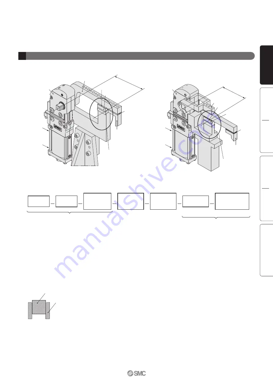
Cylinder

Arm length 

L

Shim 

w

Clamping

cylinder port

Unclamping

cylinder port

Hard stop section A

Upper hard stop

Clamping 
block

Arm length 

L

Shim 

w

Clamping

cylinder port

Unclamping

cylinder port

Cylinder

Hard stop section A

Upper hard stop

Clamping 
block

Shim 

q

Clamp arm

(Distance to a hard stop)

(Distance to a hard stop)

Clamp arm

Shim 

q


When using a hard stop


When using the side guide

Clamp arm

Side guide

2

Power clamp cylinder mounting

Series 

CKZ3N

Series 

CKZ3T


Precaution

When using the side guide to the clamp arm to prevent lateral motion, make sure not to apply a lateral load or galling to the clamp 
arm. 


Procedure

A) Supply air at clamp side without installation of upper hard stop, and operate the clamp arm to the end of clamp.
B) Under the above conditions, adjust shim 

q

 so that the space between the upper hard stop and the lower hard stop is about 0 

mm. Theoretically there is no clamping force to the lower hard stop under this condition.

C) In order to generate clamping force from the state described in step B, insert additional shim. The thickness of the shim differs 

depending on the arm length and pressure, so please refer to the graph on front matter 3 as a guide. About 10% error may occur 
due to the difference in tolerance of the power clamp cylinder body.

D) Under the state described in step C, adjust shim 

w

 so there is contact between the clamping block and the workpiece.


Mounting process

Air supply

Hard stop

set

A

Operate to the

end of clamp

Shim adjustment

B

Install the

upper hard

stop

Shim adjustment

Shim adjustment

C

Upper hard

stop contact

adjustment

Workpiece

setting

D

Block contact

adjustment

(clamp side)

Model Selection

CKZ3N

North American Type

Made to Order

European Type

CKZ3T

Front matter 4

Series 

CKZ3

Model Selection

Summary of Contents for CKZ2N Series

Page 1: ...s to standard Series CKZ3T European type Weight reduced by up to 39 7 16kg CKZ3N63 135LT 4 36kg New Unclamping angle 15 as standard 15 angle shortens clamping time and improves cycle time CKZ2N63 135LT Conventional model Power Clamp Cylinder ø50 ø63 CAT ES20 202A Series CKZ3 New New ...

Page 2: ...type Power Clamp Cylinder New New New New New Aluminum clamping body adopted Product weight reduced by up to 39 Unclamping Unclamping angle 15 as standard Rc port thread as standard Series Clamp body Bore size Made to Order specifications Iron Aluminum 50 63 80 Cylinder port G NPT Rc G NPT Unclamped opening angle 15 to 135 30 to 135 Proximity switch TURCK P F Metal cover Standard Front mounting St...

Page 3: ...n Cover Rubber Equivalent to UL94 standard V0 Flame resistant Rounded cover design reduces weld spatter accumulation Manual toggle release point Switch cassette Hexagon socket head cover cap screw Proximity cassette installation and removal easily accomplished by unfastening a single bolt Stopper bolt Conventional model Piston Simple arm opening angle changes Cylinder disassembly is not necessary ...

Page 4: ...ries CKZ3N Bumper Reduces the effects of impact from unclamping the cylinder Software CATIA UNIGRAPHICS FIDES AUTO CAD SOLID WORKS 3D CAD Series Variations Series Bore size mm Arm opening angle Switch Port thread type ø63 Equivalent ø50 Equivalent 15 30 45 60 75 90 105 120 135 TURCK P F NPT G Rc CKZ3N CKZ3T Series CKZ3N Series CKZ3T Power Clamp Cylinder For additional formats please log on to the ...

Page 5: ...ylinder mounting When clamping by using clamping force only Example Series CKZ3N Series CKZ3T Mounting process Workpiece setting Air supply Operate to the end of clamp Shim adjustment B A Install a block at clamp side Shim adjustment C Block contact adjustment clamp side Procedure A Place the workpiece supply air at clamp side without installing clamping block operate the clamp arm to the end of c...

Page 6: ...ce N 0 7 MPa 0 5 MPa 0 3 MPa Peak clamping force position 2 Power clamp cylinder mounting Relation between shim thickness and clamping force Note When a shim that exceeds the clamping force peak plotted on the graph is inserted the self locking mechanism doesn t work Insert a shim with appropriate thickness Arm length L indicates the distance between the clamp arm shaft and the clamping position F...

Page 7: ... q so that the space between the upper hard stop and the lower hard stop is about 0 mm Theoretically there is no clamping force to the lower hard stop under this condition C In order to generate clamping force from the state described in step B insert additional shim The thickness of the shim differs depending on the arm length and pressure so please refer to the graph on front matter 3 as a guide...

Page 8: ...e R L Use within the allowable arm end load range according to the distance L from the fulcrum to the mounting tool s center position and the arm opening angle θ Two side arm type D Consider the weight of allowable arm end load according to the center position G of each arm end load W1 W2 the distance L to the fulcrum and the arm opening angle θ Use within the allowable range of W1 W2 in this case...

Page 9: ... in design ø50 ø63 50 63 Y 132 138 Bore size mm Distance from pivot point L mm 150 140 130 120 110 100 90 80 70 60 50 Load capacity kg 0 0 5 1 0 1 5 2 0 2 5 3 0 3 5 4 0 4 5 5 0 5 5 6 0 Distance from pivot point L mm Load capacity kg 300 280 260 240 220 200 180 160 140 120 100 0 0 5 1 0 1 5 2 0 2 5 3 0 3 5 4 0 4 5 5 0 5 5 6 0 6 5 7 0 7 5 8 0 30 45 60 75 90 105 120 135 Arm opening angle θ 3 Clamp ar...

Page 10: ...the tightening torque shown below When mounting the clamping arm in a vertical clamping position note that the maximum angle will change 5 Remove the stopper bolt of the head cover and mount a different stopper bolt for other angles using the tightening torque below When replacing the stopper bolt fix the head cover securely If the stopper bolt is replaced without fixing the head cover the head co...

Page 11: ...60 75 90 105 120 135 R T F Proximity switch T P W TURCK P F None Front mounting Nil F No Yes M Top cover Nil M Rubber cover Metal cover CKZ Arm 63 Bore size A002 Refer to Other Clamp Cylinders on page 12 for ø80 Arm code Refer to page 3 and 8 through to 11 Arm mounting position R Right L Left D Both sides ø50 ø63 Series CKZ3N Power Clamp Cylinder Complies to NAAMS standard How to Order 50 63 ø50 E...

Page 12: ...150 mA 30 Hz PBT 2 mm 10 10 to 30 VDC N O PNP 100 mA 25 Hz PA6 PBT Green Green Clamping side Red Unclamping side Yellow Clamping side Red Unclamping side Yellow Switch Specifications Bore size mm Arm position Arm angle R L D R L D 15 3 31 3 37 4 58 4 67 30 3 29 3 34 4 55 4 64 45 3 27 3 32 4 52 4 61 60 3 25 3 31 4 49 4 58 75 3 23 3 29 4 46 4 55 90 3 21 3 27 4 43 4 52 105 3 20 3 25 4 40 4 49 120 3 1...

Page 13: ...KZ 63A019 CKZ 63A020 CKZ 63A021 CKZ 63A022 CKZ 63A023 CKZ 63A024 CKZ 63A025 CKZ 63A026 CKZ 63A027 CKZ 63A028 CKZ 63A029 CKZ 63A030 CKZ 63A031 CKZ 63A032 CKZ 63A033 CKZ 63A034 CKZ 63A035 CKZ 63A036 CKZ 63A037 CKZ 63A038 CKZ 63A039 CKZ 63A040 CKZ 63A041 CKZ 63A042 CKZ 63A043 CKZ 63A044 CKZ 63A045 CKZ 63A046 CKZ 63A047 CKZ 63A048 A001 A002 A003 A004 A005 A006 A007 A008 A009 A010 A011 A012 A013 A014 A...

Page 14: ...bolt 1Seal washer rBumper 2Bumper stopper tRubber cover 7Spacer 8Short head cap screw yMetal cover 9Metal washer 0Short head cap screw Top cover kits Stopper bolt kits Switch kits No Description Detection plate Stopper bolt Switch holder Bumper Top cover Metal cover Proximity switch Helical torsion spring Hexagon nut type 3 Switch holder gasket Hexagon socket head cover cap screw Hexagon socket he...

Page 15: ... 82 1 86 4 Cylinder Stroke Bore size mm Max clamping moment 0 3 MPa 100 300 0 4 MPa 130 350 0 5 MPa 160 400 0 6 MPa 190 450 0 7 MPa 220 500 0 8 MPa 250 550 50 63 Maximum Clamping Moment Unit N m Unit mm The moment when the clamp arm is locked at the time of air release in the clamped state Model Selection CKZ3N North American Type Made to Order European Type CKZ3T 5 Series CKZ3N Power Clamp Cylind...

Page 16: ... plug 2 x 2 x MM Depth J 2 x 2 x øPH7 Depth D Bore size mm B C D E GA GC J L LA LB MM N P GB 92 110 48 54 12 15 13 7 16 6 95 99 166 171 5 95 5 100 5 12 12 376 6 391 6 155 5 161 78 4 78 M8 x 1 25 M10 x 1 5 19 22 8 10 mm 50 63 Bore size mm PA PB PC PD R RB RC RD RR W XA XB XC RA 45 55 45 45 5 10 40 55 46 52 88 104 20 25 20 25 46 52 48 54 78 4 78 138 5 151 134 146 5 92 104 5 50 63 Dimensions 6 Series...

Page 17: ...A NB NC V VA VB VC NN 12 15 55 55 13 13 36 5 36 5 9 5 15 M8 x 1 25 M8 x 1 25 8 8 S 11 13 30 30 32 32 63 5 63 5 mm 50 63 Bore size mm LB 78 4 78 4 Y 132 138 mm 50 63 Bore size mm XA 100 5 107 5 mm 50 63 Without switch Front mounting type Metal cover type Cover open Model Selection CKZ3N North American Type Made to Order European Type CKZ3T Dimensions 7 Series CKZ3N Power Clamp Cylinder Complies to ...

Page 18: ... A 80 0 110 0 140 0 B 65 0 95 0 125 0 C 50 0 80 0 110 0 D 65 0 95 0 E 50 0 80 0 F 65 0 G 50 0 H 90 0 120 0 150 0 I 65 0 95 0 125 0 Weight kg 0 5 0 6 0 7 Part no CKZ 50A019 CKZ 50A020 CKZ 50A021 NAAMS code ACA236M ACA237M ACA238M A 80 0 110 0 140 0 B 65 0 95 0 125 0 C 50 0 80 0 110 0 D 65 0 95 0 E 50 0 80 0 F 65 0 G 50 0 H 90 0 120 0 150 0 I 65 0 95 0 125 0 Weight kg 0 5 0 6 0 7 Part no CKZ 50A022 ...

Page 19: ...80 0 110 0 140 0 B 65 0 95 0 125 0 C 50 0 80 0 110 0 D 65 0 95 0 E 50 0 80 0 F 65 0 G 50 0 H 90 0 120 0 150 0 I J 60 0 90 0 120 0 56 0 86 0 116 0 Weight kg 0 6 0 7 0 8 Part no CKZ 50A013 CKZ 50A014 CKZ 50A015 NAAMS code ACA221M ACA222M ACA223M A B 90 0 120 0 150 0 55 0 85 0 115 0 Weight kg 0 8 0 9 1 1 Part no CKZ 50A025 CKZ 50A026 CKZ 50A027 NAAMS code ACA256M ACA257M ACA258M A 80 0 110 0 140 0 B ...

Page 20: ... 0 155 0 185 0 215 0 245 0 275 0 B 110 0 140 0 170 0 200 0 230 0 260 0 C 95 0 125 0 155 0 185 0 215 0 245 0 D 80 0 110 0 140 0 170 0 200 0 230 0 E 65 0 95 0 125 0 155 0 185 0 215 0 F 80 0 110 0 140 0 170 0 200 0 G 65 0 95 0 125 0 155 0 185 0 H 80 0 110 0 140 0 170 0 I 65 0 95 0 125 0 155 0 Part no CKZ 63A007 CKZ 63A008 CKZ 63A009 CKZ 63A010 CKZ 63A011 CKZ 63A012 NAAMS code ACA007M ACA008M ACA009M ...

Page 21: ...0 0 140 0 170 0 200 0 230 0 260 0 C 95 0 125 0 155 0 185 0 215 0 245 0 D 80 0 110 0 140 0 170 0 200 0 230 0 E 65 0 95 0 125 0 155 0 185 0 215 0 F 80 0 110 0 140 0 170 0 200 0 G 65 0 95 0 125 0 155 0 185 0 H 80 0 110 0 140 0 170 0 I 65 0 95 0 125 0 155 0 J 80 0 110 0 140 0 Part no CKZ 63A031 CKZ 63A032 CKZ 63A033 CKZ 63A034 CKZ 63A035 CKZ 63A036 NAAMS code ACA031M ACA032M ACA033M ACA034M ACA035M AC...

Page 22: ... CAT E24 for details Arm mounting position R Right L Left D Both sides Cylinder Specifications ø80 Equivalent 30 to 135 Unclamping side Rubber bumper 0 8 MPa 0 3 MPa 10 to 60 C No freezing 1 0 sec to clamp 1 0 sec to unclamp TURCK P F NPT G Angle Cushion Maximum operating pressure Minimum operating pressure Ambient and fluid temperature Minimum operating time Proximity switch Port thread type Bore...

Page 23: ...0 75 90 105 120 135 T M C S Proximity switch Top cover T P W TURCK P F None CKZT Arm 63 Bore size Offset A015 A045 Offset 15 Offset 45 Symbol S B D2 9 10 2 D1 6 8 A015 Arm mounting position Mounting hole C Center R Right L Left øD1 øD2 øD1 øD2 øD1 øD2 How to Order Power Clamp Cylinder ø50 ø63 Series CKZ3T Arm mounted 50 63 ø50 Equivalent ø63 Equivalent 50 63 ø50 Equivalent ø63 Equivalent Model Sel...

Page 24: ...44 90 3 19 4 41 105 3 17 4 38 120 3 15 4 36 135 3 14 4 34 50 63 Weight Cylinder Without Arm Unit kg Note Switch specifications are corresponding to manufacturer s technical information Wiring Diagram Black S2 Lood Sensor on the clamping side S1 Lood Sensor on the unclamping side Brown White Blue 2 3 1 4 Note Both TURCK and P F are common Bore size ø50 Equivalent ø63 Equivalent Double acting Air 1 ...

Page 25: ... 1Seal washer rBumper 2Bumper stopper tRubber cover 7Spacer 8Short head cap screw yMetal cover 9Metal washer 0Short head cap screw Top cover kits Stopper bolt kits Switch kits No Description Detection plate Stopper bolt Switch holder Bumper Top cover Metal cover Proximity switch Helical torsion spring Hexagon nut type 3 Switch holder gasket Hexagon socket head cover cap screw Hexagon socket head c...

Page 26: ...50 6 75 54 8 58 7 90 62 7 66 9 105 70 4 74 8 120 77 2 81 6 135 82 1 86 4 Cylinder Stroke Bore size mm Max clamping moment 0 3 MPa 100 300 0 4 MPa 130 350 0 5 MPa 160 400 0 6 MPa 190 450 0 7 MPa 220 500 0 8 MPa 250 550 50 63 Maximum Clamping Moment Unit N m Unit mm The moment when the clamp arm is locked at the time of air release in the clamped state 16 Series CKZ3T ...

Page 27: ...1 11 8 8 30 30 32 32 63 5 63 5 71 5 71 5 VE 12 12 VF 3 5 3 5 W 78 4 78 XA 138 5 151 XB 134 146 5 XC 92 104 5 50 63 4 x NN Depth S VC 0 1 VD 0 05 VB 0 1 VE N9 2 x øV H7 Depth I C 2 x 2 x NPT 1 4 G Rc NC NB 0 05 R W PC 0 05 PA 0 02 PB 0 02 PD 0 05 LA 0 1 L Pivot point with square flats Nh9 Release point 2 x 2 x MM Depth J 2 x 2 x øPH7 Depth D RA RR R GC GB GA RB XA XB XC LB E B NA 0 05 VA 0 02 VF K ...

Page 28: ... Release point LB Y XA Cover open Leave sufficient space to open and close the metal cover when operating the manual release Bore size mm LB 78 4 78 4 Y 132 138 mm 50 63 Bore size mm XA 100 5 107 5 mm 50 63 Dimensions 18 Series CKZ3T ...

Page 29: ...A015RB CKZT50 A015LS CKZT50 A015LB 0 79 kg 0 78 kg 0 90 kg 0 89 kg 0 90 kg 0 89 kg CKZT50 A015 C Arm position C R L Center Right Left S Mounting hole S B D1 6 8 D2 9 10 2 Symbol How to Order Weight CKZT63 A015CS CKZT63 A015CB CKZT63 A015RS CKZT63 A015RB CKZT63 A015LS CKZT63 A015LB 1 02 kg 1 01 kg 1 10 kg 1 08 kg 1 10 kg 1 08 kg CKZT63 A015 C Arm position C R L Center Right Left S Mounting hole S B...

Page 30: ... CKZT50 A045 C Arm position C R L Center Right Left S Mounting hole S B D1 6 8 Symbol D2 9 10 2 How to Order 37 47 20 54 78 28 0 1 45 0 2 144 22 64 30 0 2 30 0 02 105 0 1 Center type Left type Right type 2 x øD1H7 through 2 x øD2 through 9 Weight CKZT63 A045CS CKZT63 A045CB CKZT63 A045RS CKZT63 A045RB CKZT63 A045LS CKZT63 A045LB 1 19 kg 1 18 kg 1 25 kg 1 23 kg 1 25 kg 1 23 kg How to Order CKZT63 A...

Page 31: ...Angle adjustment bolt Angle scale Series Angle Special product number CKZT25 105 CKZT25 105 DCL781EL Bore size mm ø25 105 Unclamping side Rubber bumper 0 8 MPa 10 to 60 No freezing 1 0 sec to clamp 1 0 sec to unclamp 0 58 kg Angle Cushion Maximum operating pressure Ambient and fluid temperature Minimum operating time Weight without arm Cylinder Specifications Bore size mm ø40 ø50 Equivalent ø63 Eq...

Page 32: ...sec to unclamp Angle Cushion Maximum operating pressure Ambient and fluid temperature Minimum operating time Cylinder Specifications Bore size mm ø25 ø50 Equivalent ø40 ø63 Equivalent ø80 Equivalent 30 45 60 75 90 105 120 30 45 60 75 90 105 105 Unclamping side Rubber bumper 0 8 MPa 10 to 60 No freezing 1 0 sec to clamp 1 0 sec to unclamp Angle Cushion Maximum operating pressure Ambient and fluid t...

Page 33: ...amping side Rubber bumper 0 8 MPa 0 3 MPa 10 to 60 C No freezing 1 0 sec to clamp 1 0 sec to unclamp TURCK P F NPT G ø80 Equivalent ø40 Angle Cushion Maximum operating pressure Minimum operating pressure Ambient and fluid temperature Minimum operating time Proximity switch Port thread type Bore size øD1 H øD2 Arm mounting position Mounting hole R Right C Center L Left H øD1 øD2 H øD1 øD2 Features ...

Page 34: ...s other than replaceable parts otherwise it may reduce the performance of the clamp cylinder 3 Tightening torque of spare parts Please make sure to tighten spare parts recommended in accordance with the following torque shown in the table 4 Clamp arm tightening torque 50 63 50 63 50 63 50 63 2 6 to 3 5 2 6 to 3 5 130 to 150 160 to 200 1 5 to 2 0 1 5 to 2 0 1 5 to 2 0 1 5 to 2 0 Bore size mm Tighte...

Page 35: ...peration Warning Limited warranty and Disclaimer Compliance Requirements The product used is subject to the following Limited warranty and Disclaimer and Compliance Requirements Read and accept them before using the product 1 The product is provided for use in manufacturing industries The product herein described is basically provided for peaceful use in manufacturing industries If considering usi...

Reviews: