background image


41 


SVC400P/SVC800P    -    User Manual 


5.3.2 HISTORY 

The data for history information   


Summary of Contents for SVC400L

Page 1: ...1 SVC400L SVC400P SVC800P Mobile Video Recorders User Manual ...

Page 2: ...a more efficient method of storing data by taking up less hard disk space 4 8 channels for high fidelity digitally recorded synchronized audio matched to 4 8 video channels User friendly criteria to playback the events associated video only Automatic timer to resume the live display if the unit is idle for user defined timings User selectable settings for quality and audio record enable disable fo...

Page 3: ...VC400P SVC800P User Manual 1 2 PRODUCT SOLUTION Passenger statistic LED IR control Control center CMS client Playback software GPRS CDMA EDGE 3G Wireless transmission Station Announcement Camera Live view ...

Page 4: ...CONTROL KEY FUNCTIONS Numeric Input Keys Use the numbers to input values in the system setup screen or switch through the channels in live mode and playback and buttons are used to increase setup values one by one Navigation Arrows Use the ARROW keys to move between selections input fields and icons Press ENTER to select and EXIT to return Next and previous are used to increase or decrease volume ...

Page 5: ... SETUP key to enter the user setup It is important to remember the password due to without restoration function POWER The Power button can reset the DVR in to sleep mode unit will stop recording while in the sleep mode VGA Switch the output mode to VGA Include VGA1 VGA2 VGA3 VIDEO Switch back from VGA to composite output V1 Swapping between multi channel and single channel monitor While in surveil...

Page 6: ...e volume while playback if audio is recorded or multimedia playback PREV Decrease volume while playback if audio is recorded or multimedia playback REW Rewinds the video while playback X2 and X 4 modes available FWD Fast forward the video while playback X2 and X4 modes available CF No use at present F1 F2 F3 F4 Reserved for future use 4 PAN TILT ZOOM FUNCTIONS While connect with PTZ camera and usi...

Page 7: ...7 SVC400P SVC800P User Manual 3 MENU TREE Menu structure tree ...

Page 8: ...ll automatically start recording Power is normally supplied to the DVR as long as the vehicle ignition is ON Display only view of the cameras is immediately available to be viewed in quad view SYSTEM LOGIN FOR SETUP When Password is set to disable press SETUP key on the handheld controller into the setup menu directly When Password is set enable press LOGIN LOCK OR ENTER key on the handheld contro...

Page 9: ...exit to the live view The DVR will stop recording when enter into the configuration GUI You can input the letters and characters by software keyboard DEVICE NO The identification number of DVR you can set the ID in the GUI PASSWORD Enter the admin password or user password Keyboard Press Enter to use keyboard to type device ID and password 1 0 9 number key press Enter to select the number 2 123 In...

Page 10: ...TYPE The type of the file including alarm file and normal file DATE DVR system will display the current day automatically The day with record files will be indicated by green If the day with ALARM FILES it will indicated by yellow TIME The default setting is 00 00 00 this time is for the start time for recording For example If the date is 2009_04_14 and the time is 00 00 00 it indicates that you w...

Page 11: ...s SEARCH to enter into the next menu for listing out all the certain video files depends on the setting or the file type date and time SEL For selecting the files for backup Please press arrow key on remote control to select the file that need to back up and then will display REV Press for selecting all or not For example if you do not select any file for backup then press REV all the files are se...

Page 12: ...g backed now After successful backup then the following screen will pop up If the DVR current video type is different with the setting that the DVR last recorded then the video file will not playback For example the video type of recorded files is in NSTC but now the video type is changed to PAL then you won t be able to playback the video file until you change the video type to NSTC The user will...

Page 13: ...ES Search for all the event files LOG not video file FILE TYPE The type of the alarm file including I O ALARM ACCELERATION SPPED TEMP ALARM VL ALARM DATE The system will display the current date automatically Any date with alarm recorded files available to use will be indicated by yellow Please press SEARCH to enter into the next menu and will display the results as follows ...

Page 14: ...ed up and then will display Please press REV to select all the files for backup or not EVENT NAME The type of alarm event such as alarm for video loss alarm for over speed low speed or high temperature sensors etc DATE Display the date when the alarm occurred TIME The start time when the alarm occurred REV Press for selecting all or not for example if you do not select any files for backup then pr...

Page 15: ...15 SVC400P SVC800P User Manual 5 2 SETUP Use ARROWS on the remote control to select SYSTEM and then press ENTER The screen will show the menu as below 5 2 1 SYSTEM ...

Page 16: ...e NTP Network Time Protocol the device must have network access connection and assign the NTP IP location This process run at 6 30am local time while the system have network connection TIME ZONE Please choose the correct time zone where the vehicle is located SYNC TIME This is the time when the unit will sync the system time every day The method depends on the setting on the TIME SYNC SOURCE optio...

Page 17: ...B TIMER It will start up automatically at the time your setup If you select TIMER then the following screen will pop up BOOT UP TIME The exact time for DVR starts to work every day SHUT DOWN TIME The exact time for DVR shut down every day BOOT UP IN RECORDING TIME ON refers to the record function being linked to the timer start up i e if the setting for BOOT UP TIME is 06 00 00 the DVR will start ...

Page 18: ...rm the changes C REGISTER INFO UNIT S N The series Number for DVR One DVR has only one S N This number is taken from a special encrypted chip UNIT ID Device ID Use the NUMERIC keypad to enter the system ID from 00000 to 99999 This ID is used when logging in to the unit if security is enabled set as yes COMPANY NAME The name of company Press the arrow key on the remote control and highlight this op...

Page 19: ...t to format HDD SD card or external USB storage device DEVICE Please press ENTER to select the target device for format There are 3 options HDD SD and USB Then press FORMAT to format the storage device After formatting successfully the unit will restart automatically ...

Page 20: ...rupgrade in thumb drive and then copy the firmware upgrade file into this folder 2 Insert the thumb drive into the USB port on the front panel of DVR 3 Please enter into this interface and press UPGRADE DVR will upgrade the firmware automatically 4 During the firmware upgrade then following screen will pop up 5 After upgrade successfully the unit will restart automatically as follows ...

Page 21: ...grade Please check the firmware version after the unit has rebooted up and make sure that the firmware upgrade is completely successful If the firmware of the DVR is the latest then you can not upgrade the firmware again And DVR system will display the following screen MCU UPGRADE The step is the same as upgrade firmware ...

Page 22: ...FF will not require a password in order to access the setup menu USER PASSWORD Users can only search and won t be able to modify any parameters ADMIN PASSWORD An Administrator with full rights Re enter must be same input as first password otherwise the system would not accept the password setting when password does not match between the first line and re enter line Then the following screen will p...

Page 23: ... port and then press EXPORT Then the configuration file will backup to external device IMPORT Import the DVR configuration file to the current device except MAC address and IP Please insert the external USB storage device to the USB port Must have configuration file in the storage device and then press IMPORT The configuration will import to another DVR automatically RESTORE Restore default settin...

Page 24: ...L and NTSC optional The default setting is NTSC RECORD MODE Record mode three modes as following GENERAL When DVR is powered and starts up the unit will start to record automatically TIMER DVR will start to record at defined time setting in the TIMER RECORD menu based on the schedule EVENT When event trigged DVR will create event record ...

Page 25: ...ALARM POST REC 30 1800 SEC alarm post recording time setting BUZZER ALARM TIME buzzer alarm duration time setup when alarm triggered the buzzer duration time MEDADATA CAPTURE metadata information M D REC WHEN IGNITION OFF Active the Motion Detection function when the ignition is OFF MIRROR REC TO SD CARD Active Mirror function SD card and HDD can record at the same time HDD record based on high re...

Page 26: ...tus on live view DATE TIME Display date and time on OSD ALARM Display Alarm information on OSD MODULE STATUS Display the module status including wireless module CDMA GPRS EDGE 3G and WIFI ACCELERATION Display the information for inertial sensor TEMPERATURE Display the temperature on OSD FIRMWARE VERSION Display the current firmware version GPS Display the GPS working status If all the options are ...

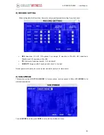
Page 27: ...the record function NAME The name of the channel For example if you setup the name of CH1 is ABC and you can see ABC three letters display on the live view for channel 1 AUDIO Active the audio record function LIVE to display the live view ROUND Means channel loop function display the channel as full screen in round time ...

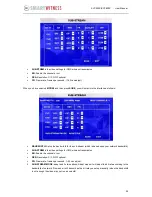
Page 28: ...88 and CIF resolution is 354 288 FR Frame rate frames per second 1 25 can adjust QUANLITY Image quality 8 levels optional Level 1 is the best Normal quality is the quality for normal record and alarm quality is for alarm record E SUB STREAM There are two modes SUB STREAM MODE 1 is for connections such as connect in LAN or WIFI MODE 2 is for wireless transmissions To select MODE1 and then press SUR...

Page 29: ...DTH Setup the band width for the sub stream which is based upon your network bandwidth SUB STREM is the video settings for CMS wireless transmission EN Enable the channel or not RES Resolution CIF QCIF optional FR Frame rate frames per second 1 25 can adjust SUB STREAM MODE adapt and fix two options Adapt means it will adjust the bit rate according to the bandwidth of network Fix means it will tra...

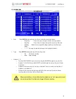
Page 30: ...nly apply Weekdays weekday is from Monday to Friday o Choosing the asterisks will suspend the highlighted schedule Type Press ENTER to change the type of the recording mode o Con Continuous recording o Alarm Alarm recording Schedule 1 2 o Press the RIGHT ARROW key to enter values using the NUMERIC keypad into any time field o Schedule 1 is the first of two possible ON OFF cycles that apply to any ...

Page 31: ...31 SVC400P SVC800P User Manual G OTHER SET This interface is for you to setup the watermark as follows 5 2 3 NETWORK ...

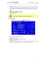
Page 32: ...ocal Internet Service Provider for this information Use NUMERIC keypad to enter the TCP IP address information IP Enter the static IP address SUB Enter the subnet mask GATE Enter the gateway that the DVR through to network CLIENT PORT and WEB PORT no use at present MAC Address MAC address is uniquely and cannot change it B SERVER NETWORK The sever IP and port setting for VMS and CMS software ...

Page 33: ... is used in LAN by WIFI or local network or via 3G wireless module PORT please use the default port 5556 here VMS MEDIA IP AND PORT NO use at present CMS NO use at present C WIFI SETUP IP Enter the static IP address of built in WIFI SUB Enter the subnet mask GATE Enter the gateway that the DVR through to network ESSID The AP name of this WIFI GET IP TYPE There are two options STATIC IP means you h...

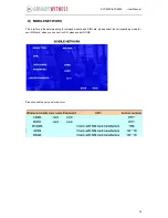
Page 34: ...anual D MOBILE NETWORK This interface is the network setup for wireless module and SIM card please select the corresponding mode for your SIM card when you connect in LAN please select NONE Please check the setup as follow form ...

Page 35: ...or connected to the unit OSD Input the numbers and Characters they will be embedded into the alarm video files when alarms happen and it will also display in live view Please press ENTER into the soft keyboard The label also identifies the type of event when doing a quick search using EVENT SEARCH option SET LOW normal close means high to low trigger alarm HIGH normal open means low to high trigge...

Page 36: ...hard disk B SPEED Setup the alarm for over speed and some other parameters SOURCE DVR is capable of capturing vehicle speed via GPS antenna or Vehicle speedometer o Browse between the settings of GPS or speedometer from the list o Please note that the GPS antenna should be connected to DVR to receive satellite signals for speed o For more information on capturing speed from speedometer please cont...

Page 37: ...DVR will trigger the alarm signal when the following option ALARM set as YES until the Admin password is entered to acknowledge the alarm E ACCELERATION There are 3 values for G force inertial sensor X Y and Z X indicate forward and backward X Y indicates left and right and Z indicated up and down Threshold is the limitation for the value if the value large than the setting in the menu then DVR wi...

Page 38: ...the DVR working temperature is higher than the setting for HIGH TEMP DVR will alarm If the DVR working temperature is lower than the setting for LOW TEMP DVR will alarm G CAMERA Display the alarm information from camera CH ID Channel number VIDEO LOSS Alarm for video loss Only the log for alarm but no video file saved ...

Page 39: ...witch and the default is Pelco D BAUD RATE select the different baud rate for your PTZ there are 1200 2400 4800 and 9600 DATA BIT there are 5 6 7 8 options to select default setting is 8 STOP BIT there are 1and 2 to select the default setting is 1 VERIFY there are None Odd Even Mark Space to select the default setting is none ADDRESS Fill the code of respective PTZ ...

Page 40: ... INFORMATION 5 3 1 SYSTEM Display the MCU version firmware version HDD status and SD card information o NO HDD means No HDD installed or the HDD is defective and can not work o NO FORMAT means HDD installed but not formatted o showing the detailed information for HDD means HDD works fine ...

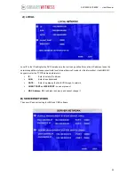
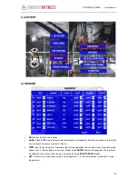
Page 41: ...41 SVC400P SVC800P User Manual 5 3 2 HISTORY The data for history information ...

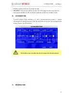
Page 42: ...42 SVC400P SVC800P User Manual Press CLEAR to delete all the current data 5 3 3 MODULES Display the module information GPS GPRS CDMA EDGE 3G and WIFI ...

Reviews: