


ST-2112D SM R 1.2 SMARTRUNK SYSTEMS, INC.
17
5.5.2.
Transmit Power alignment:
ST-2112 has three power levels to
be selected for each channel. High,
medium and low power level can be
aligned as per radio usage
requirement.
For power alignment, you can do a
fine tuning as per your desire
frequency sub-band. The software
lets you linearize the complete band
“cutting” the complete band into
five steps to let you focus into your
frequency bands.
Even when the software has already
assigned the most convenient
frequency points to consider the
alignment, you still can enter
exactly the frequency of your
interest.
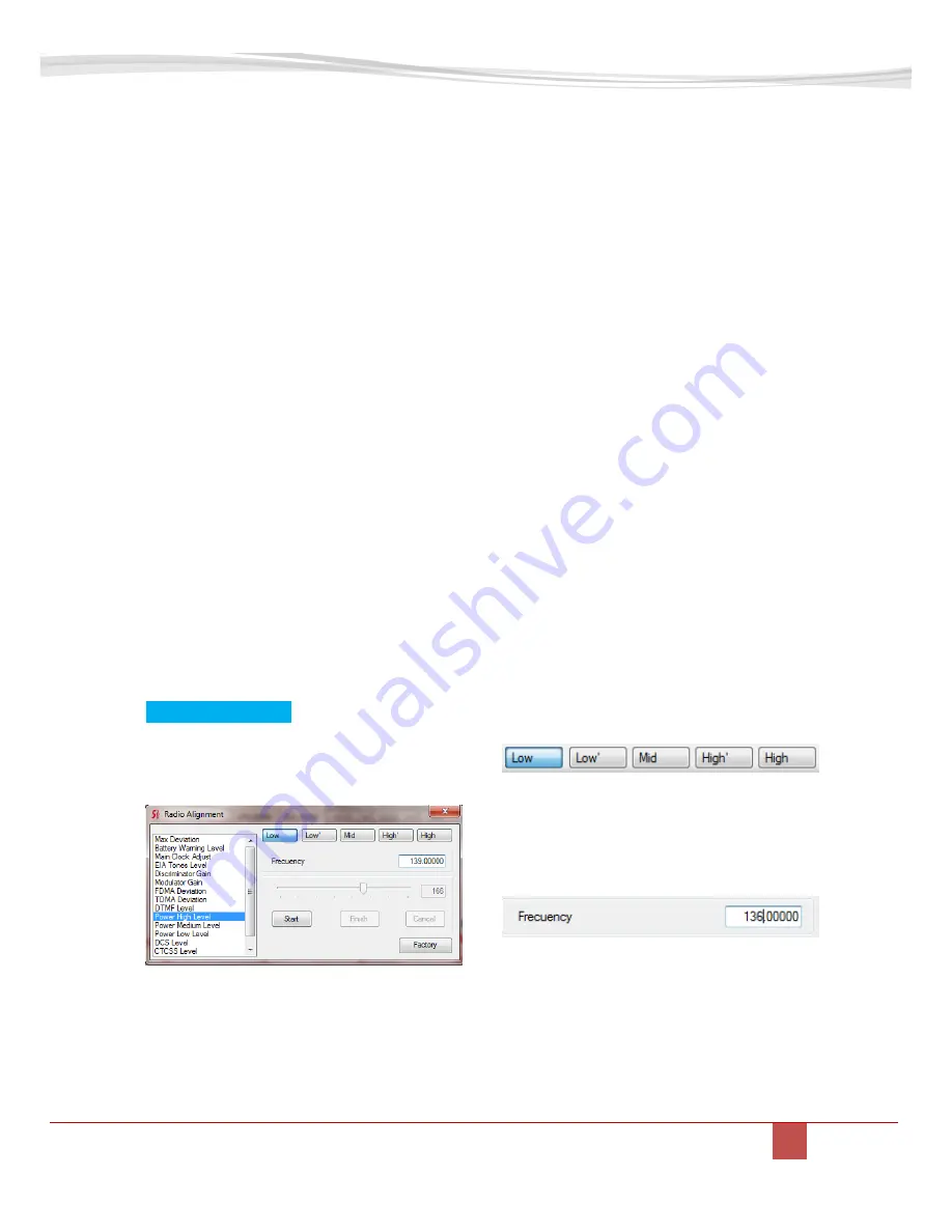
5.5.2.1.
High POWER LEVEL
ALIGNMENT
To align the High Power level select
Power High Level.
Software automatically retrieves
actual level to the alignment slider.
This level has been aligned in
factory, but you still can adjust it as
per your desires.
To realign, please select [Start] then
move the slider or introduce the
value manually at the time you
check the real transmit power on
the wattmeter connected to the
radio as recommended on TX
alignment diagram.
As soon as [Start] is pressed, the
radio start to transmit a carrier, so
please verify the antenna dummy
load is properly connected to avoid
any damage to the transmitter.
As soon the desired value is
reached, press [Finish] to store the
value into radio memory.
If you want to load default High
power only, keeping any other value
without any change, press [Factory]
instead of [Start]. A pop up window
will ask you to confirm the default
parameters upload to the radio
power.
Press [OK] to confirm.
As descripted previously, you can
manually select the frequency
range to align, divided into five
different sub-ranges.
You can also define the right
frequency of interest to align, typing
the desired one into the frequency
field:
If selected frequency is not
supported by radio hardware, the
frequency field will be filled on red.
In case the PLL is locked, then it
becomes filled on green.
Please be sure that the PLL is
locked as soon as you press [Start],
Summary of Contents for ST-2112D
Page 6: ...2 ST 2112 EXPLODED VIEW ST 2112V Jack Chang Daniel Martin 2 ST 2112 EXPLODED VIEW ...
Page 8: ...Notes ...
Page 31: ...ST 2112D SM R 1 2 SMARTRUNK SYSTEMS INC 31 This page left blank intentionally ...
Page 34: ...11 ST 2112 COMPONENT LOCATOR TOP LAYER ...
Page 35: ...ST 2112D SM R 1 2 SMARTRUNK SYSTEMS INC 35 12 ST 2112 COMPONENT LOCATOR BOTTOM LAYER ...
Page 36: ...ST 2112D SM R 1 2 SMARTRUNK SYSTEMS INC 36 13 ST 2112 PCB TOP LAYER ...
Page 37: ...ST 2112D SM R 1 2 SMARTRUNK SYSTEMS INC 37 14 ST 2112 PCB BOTTOM LAYER ...
Page 38: ...ST 2112D SM R 1 2 SMARTRUNK SYSTEMS INC 38 15 ST 2112 PCB GROUND LAYER ...
Page 39: ...ST 2112D SM R 1 2 SMARTRUNK SYSTEMS INC 39 16 ST 2112 PCB POWER LAYER ...
Page 40: ...ST 2112D SM R 1 2 SMARTRUNK SYSTEMS INC 40 17 ST 2112 FRONT BOARD COMPONENT LOCATOR TOP LAYER ...