background image

Longo programmable controller LPC-2.DI6

STANDARDS AND PROVISIONS: Standards, recommendations, regulations
and provisions of the country in which the devices will operate, must
be considered while planning and setting up electrical devices. Work
on 100 .. 240 V AC network is allowed for authorized personnel only.

DANGER   WARNINGS:   Devices   or   modules   must   be   protected   from
moisture, dirt and damage during transport, storing and operation.

WARRANTY   CONDITIONS:   For   all   modules   LONGO   LPC-2   –   if   no
modifications   are   performed   upon   and   are   correctly   connected   by
authorized   personnel   –   in   consideration   of   maximum   allowed
connecting power, warranty of 24 months is valid from the date of sale
to the end buyer, but not more than 36 months after delivery from
Smarteh. In case of claims within warranty time, which are based on
material   malfunctions   the   producer   offers   free   replacement.   The
method of return of malfunctioned module, together with description,
can be arranged with our authorized representative. Warranty does
not   include   damage   due   to   transport   or   because   of   unconsidered
corresponding   regulations   of   the   country,   where   the   module   is
installed.
This device must be connected properly by the provided connection
scheme in this manual. Misconnections may result in device damage,
fire or personal injury.
Hazardous  voltage   in  the  device  can  cause   electric  shock  and  may
result in personal injury or death.
NEVER SERVICE THIS PRODUCT YOURSELF!
This device must not be installed in the systems critical for life (e.g.
medical devices, aircrafts, etc.).

If the device is used in a manner not specified by the manufacturer,
the degree of protection provided by the equipment may be impaired.

Waste electrical and electronic equipment (WEEE) must be collected
separately!

LONGO LPC-2 complies to the following standards:

EMC: EN 61000-6-3:2007 + A1:2011, EN 61000-6-1:2007, EN 61000-
3-2:2006 + A1:2009 + A2: 2009, EN 61000-3-3:2013

LVD: IEC 61010-1:2010 (3

rd

 Ed.), IEC 61010-2-201:2013 (1

st

 Ed.)

Smarteh   d.o.o.   operates   a   policy   of   continuous   development.
Therefore we reserve the right to make changes and improvements to
any of the products described in this manual without any prior notice.

MANUFACTURER:
SMARTEH d.o.o.
Poljubinj 114
5220 Tolmin
Slovenia

ii

Summary of Contents for LPC-2.DI6

Page 1: ...USER MANUAL Longo programmable controller LPC 2 DI6 Digital Input module Version 5 SMARTEH d o o Poljubinj 114 5220 Tolmin Slovenia Tel 386 0 388 44 00 e mail info smarteh si www smarteh si...

Page 2: ...Longo programmable controller LPC 2 DI6 Written by SMARTEH d o o Copyright 2012 SMARTEH d o o User Manual Document Version 005 July 1 2012 i...

Page 3: ...ot include damage due to transport or because of unconsidered corresponding regulations of the country where the module is installed This device must be connected properly by the provided connection s...

Page 4: ...er LPC 2 DI6 Longo programmable controller LPC 2 DI6 1 DESCRIPTION 1 2 FEATURES 2 3 INSTALLATION 3 3 1 Connection scheme 3 3 2 Mounting instructions 5 3 3 Module labeling 6 4 TECHNICAL SPECIFICATIONS...

Page 5: ...f the LPC 2 system It can be used in a wide range of operation where sensors and devices connected to the LPC 2 DI6 module provide 24 V DC signals required for inputs activation LEDs indicate active s...

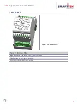
Page 6: ...controller LPC 2 DI6 2 FEATURES Figure 1 LPC 2 DI6 module Table 1 Technical data Eight external 24 V DC digital inputs galvanic isolated Flexible input for wide use of operation Standard DIN EN50022...

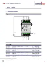
Page 7: ...0 24 V DC 24 V DC digital input IN2 4 I Reference Reference to 24 V DC IN3 5 I Digital input in reference to IN3 6 0 24 V DC 24 V DC digital input IN3 6 I Reference Reference to 24 V DC IN4 7 I Digit...

Page 8: ...ference to IN8 16 0 24 V DC 24 V DC digital input IN8 16 I Reference Reference to 24 V DC Table 3 Digital input specification IN1 1 IN8 15 Digital input reference to IN1 2 up to IN8 16 0 24 V DC Rin 3...

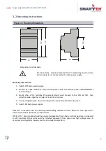
Page 9: ...equired Mount each module to the DIN rail first then attach modules together through K1 and K2 connectors 4 Connect digital inputs wires according to the connection scheme in Figure 2 5 Switch ON main...

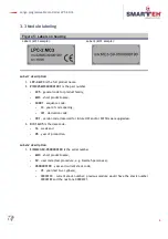
Page 10: ...e code 04 year of code opening 001 derivation code 001 version code reserved for future HW and or SW firmware upgrades 3 D C 16 05 is the date code 16 week and 05 year of production Label 2 descriptio...

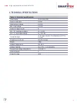
Page 11: ...oltage 35 V DC Number of digital inputs 8 Off 0 input signal voltage Uin 2 V DC On 1 input signal voltage Uin 15 V DC Connection type screw type connector for stranded wire 0 75 to 2 5 mm2 Dimensions...

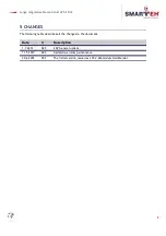
Page 12: ...5 CHANGES The following table describes all the changes to the document Date V Description 1 7 2012 005 CGP General update 11 5 2010 004 Updated warranty permanence 30 6 2005 003 The initial version...

Page 13: ...Longo programmable controller LPC 2 DI6 6 NOTES 9...

Reviews: