


Page 6 of 32
9.
Click on the boxes, as shown, and then
choose “Negative” for the three voltage
settings. Click on “Finish” to keep these
settings.
10.
Click “OK” at bottom of the “Power Options Properties” window to finish.
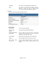
2.3 Daisy Chain Setup Procedure
The Remote Power Manager (RPM) can be Daisy Chained up to a maximum of sixteen units.
Each RPM in the Daisy Chain must have its own unique identification number. The default
ID# is “0 “. The first RPM must have the Internet Power Management Card install and must
be configured before you can begin Daisy Chaining any additional RPMs. Only the first
RPM requires the Internet Power Management Card. All of the other RPMs in the Daisy
Chain do not require that the Internet Power Management Card be installed. Follow the
procedure below to Daisy Chain the RPMs:
Figure 1 - First RPM
1.
Make sure that the Terminator is plugged into the first RPM's iLink port (see Figure 1).
2.
Plug the first RPM's power cord into utility power.
3.
Turn the master power switch on.
4.
Setup the RPM (see Setup Procedure page 9).
5. Configure the first RPM's ID number (each RPM must have it's own unique ID#, the
default ID# is "0").
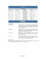
Figure 2 - First and second RPM
6. Make sure that the second RPM has the Terminator plugged into the iLink port (see
Figure 2).
7.
Connect the first and second RPM together with the iLink cable.
8.
Plug the second RPM's power cord into utility power.
9.
Turn the master power switch on.
10. Configure the second RPM's ID number (each RPM must have it's own unique ID#, the
default ID# is "0").
11. If there are only two RPMs required for this application, then this completes the Daisy
Chaining procedure and the RPMs are ready for use.