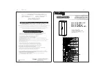
With help, lift the first of 3 table sections into position over base and legs
At this time, double-check the position of the Cylinder base, such that it captured the power and data source in the floor.
Locat the 3 legs, as nearly you can, to support the table section, then lift the table section into place.
Secure Legs to Top
Use two 1/4-20 hex head
bolts to secure the leg to the
inserts installed in the table
top. Keep this loose until the
table sections are fully joined
using the Cam Lock Joiners.
Repeat Installation of Keyboard Trays and CPU Tracks
Lift Table Section Into Position
You will again use 14-20s to install the legs to the top inserts.
Again: keep it loose!
Install the Cam Lock Joiners
Spin the C to a snug position,
place the Cam into the Cam
Lock. Turn the Cam Lock a
quarter turn to the right.
Work Together
This process is done to
unitize the table sections.
While one installs the two
Cam Lock Joiners, the other
ensures the seam is mini-
mized.
When the seam is done,
tighten the 1/4-20s in the
seam’s leg plate.


