background image

Hussar Robot Chassis Manual 


Smart Restaurant Solutions 


10 


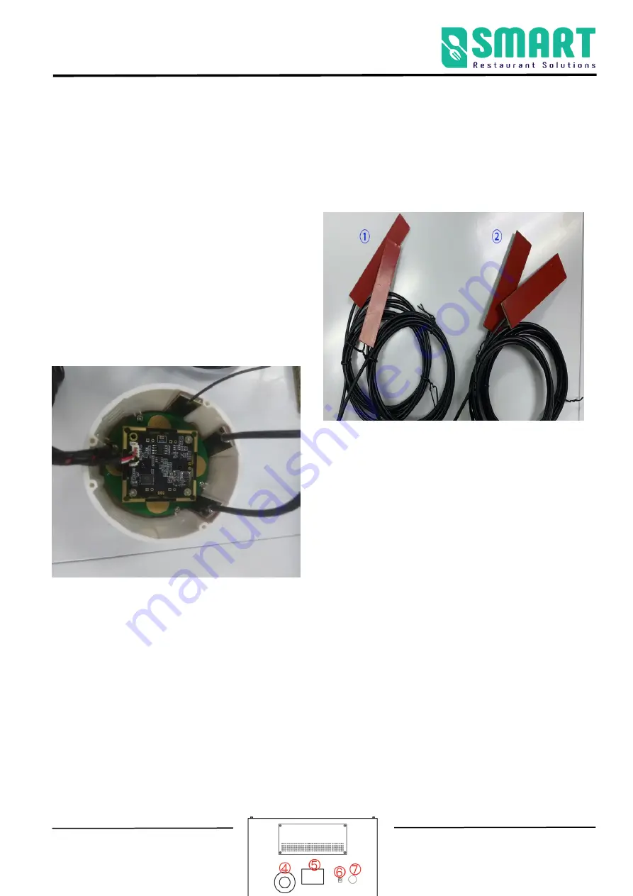
Installation of 4G router main and secondary antenna 

Note: The antenna cannot be pasted on metal parts, nor can it be pasted in the surrounding metal part 

shielding  cover;  it  should  be  pasted  on  the 

surrounding  plastic  parts  to  prevent  the  antenna 

signal  from  being  shielded  by  the  metal  parts.  (It 

can also be pasted inside the infrared vision camera 

module shell)


4G router secondary antenna             

4G router main antenna


2

Use your robot 

A. Boot 

The power button is located on the base 

  on the back of the robot. It is 

a button switch. Press it once to turn it on, and press and hold the power 

button for 3 seconds to turn it off. 

Summary of Contents for Hussar

Page 1: ...ns 1 Hussar Robot Chassis Manual Version 2 1 4G Date 2022 1 6 Note This document provides the deployment process and precautions related to the machine Follow the instructions in the document to avoid...

Page 2: ...meters 5 Meet your robot 5 2 Use your robot 7 1 Boot 7 2 Charging 8 3 Navigation deployment 10 The step 1 Connect to the Internet 10 The step 2 Build a map 12 The Step 3 Position 19 The step 4 Virtual...

Page 3: ...Hussar Robot Chassis Manual Smart Restaurant Solutions 3...

Page 4: ...lack marble and black reflective cabinets at the floor height of 30 cm Do not travel on the ground with high friction thicker softer carpet Do not use in an environment with a slope greater than 5 Do...

Page 5: ...temperature 15 C 55 C Working temperature 10 C 50 C Humidity RH 10 90 Infrared camera Two dimensional code positioning the height of the two dimensional code from the camera is 1 3m or 1 5m 5 million...

Page 6: ...ope sensor Yaw angle measurement hard disk 32G high speed solid state drive motor driven 5 5 inch hub motor Infrared sensor Communicate with charging piles within 1 meter 4G router to 2 4GWIFI 4GCPE M...

Page 7: ...harging pile parameters Overcurrent protection intelligent power off output rated voltage 42VDC output rated current 5A Remote function Support remote video monitoring remote navigation status monitor...

Page 8: ...sor In line power hole Power button Automatic charging shrapnel Uitrasound Cleaning precautions Laser navigation please do not wipe it with a wet towel toavoid water ingress Precautions for use Laser...

Page 9: ...t Chassis Manual Smart Restaurant Solutions 9 Hardware structure Usb board Android Wi Fi cable master computer Red 12v Black GND Speaker Visual infrared camera 4g Router secondary antenna 4g Router ma...

Page 10: ...be pasted on the surrounding plastic parts to prevent the antenna signal from being shielded by the metal parts It can also be pasted inside the infrared vision camera module shell 4G router secondar...

Page 11: ...g Get to know your charger The adapter plug needs to be plugged into the 110 220 V voltage and the DC head is plugged into the automatic charging pile At this time the green light of the charging pile...

Page 12: ...Robot Chassis Manual Smart Restaurant Solutions 12 Direct charging plug the power adapter cable into the power supply on the back of the robot Automatic charging hardware description Charging post pla...

Page 13: ...ging pile C Navigation deployment Note The following content is an introduction to all the functions of the robot deployment background The functions that must be operated are as shown in points 1 2 3...

Page 14: ...k segment cannot be the 192 168 10 x network segment 1 Open the Settings WLAN on the Android screen of the robot to connect to Wi Fi 2 Open the Ftp application and enter the following interface Follow...

Page 15: ...t click once don t click repeatedly If show IP connection succeeds If shows 127 0 0 1 connection fails 3 The scanning device should be connected to the same LAN as the robot Open the browser and input...

Page 16: ...and construct an original map During the navigation process the robot can compare with the original map based on the real time scanning situation and find its own position The viewing angle of the Lid...

Page 17: ...construction It is recommended to build a non label map If the robot is lost during the use process please contact the technician in the group to investigate the specific reasons 1 Please follow the...

Page 18: ...around to clear the surrounding feature points And don t turn it too fast You can push control the robot after one turn You can walk straight in narrow areas Pay attention to the gaps during walking...

Page 19: ...aser and terrain some areas need robot to turn to be able to scan clearly such as wide terrain and room 4 Do not move the machine after the machine reaches the end point Just observe whether the map i...

Page 20: ...r to match the current terrain 3 After the robot reaches the destination observe whether the map is clean without ghosting and matches the actual terrain If there is no obvious dislocation click compo...

Page 21: ...ere should be no big obstructions above the robot s road so that the machine fail to see the QR code on the road 4 Ceiling to camera height between 1 m and 5 m 5 The QR code should be pasted in the mi...

Page 22: ...and then tear the transparent surface taking care not to drop the round or ring spots during the tearing process after completion as shown in Figure 3 Note Paste the QR code in the place designated b...

Page 23: ...on provide reachable target points for business layer applications Note The calibrated position must be at least 50 cm away from surrounding obstacles and virtual walls the machine must be turned on w...

Page 24: ...te and the icon will automatically move forward when the calibration occurs note only this point is the exception Calibration list Click on the right side of the screen to pop up this location list an...

Page 25: ...and right sides of the charging_pile The step 4 Virtual wall Edit the function of virtual wall restrict the active area of robot DRAG in this mode you can zoom pan and rotate the map In this mode you...

Page 26: ...tual wall that needs to be cleared SAVE only click Save to save the drawn virtual wall CLEAR if you are not satisfied with the current virtual wall click the clear button to clear all the virtual wall...

Page 27: ...environment figure 2 Map scanned by laser figure 3 error figure 4 correct matters needing attention 1 The minimum passing distance of the machine is 80cm so attention should be paid when drawing the...

Page 28: ...bjects etc please make sure to build virtual walls 3 Explanation of other functions a Special Area Function The drawable area limits the speed of the robot in a certain area EDIT In the map click with...

Page 29: ...rea list will pop up on the right side of the page You can redefine the speed and name of the area in the area list and delete the area CLEAR ALL Refers to one key to clear all edited special areas No...

Page 30: ...les in the map such as temporary people etc during the process of scanning the map Do not remove the real obstacles Blocked area some real fixed obstacles may not be scanned very clearly when building...

Page 31: ...the same way as a special area the interior of the drawn polygon is a modified area c Map Edit map name Apply this map Export the map to the computer Delete this map Mouse over to show preview map cli...

Page 32: ...Smart Restaurant Solutions 32 d Upgrade Tip We will upgrade to the latest version before leaving the factory and later if you need to update the version follow the following methods Apply this version...

Page 33: ...port the pgm file to be combined Import Import the assembled pgm file Generate a new map click to generate a new map Power board upgrade when it ship out of factory is latest version no need to update...

Page 34: ...map 2 to map 1 to get map 3 import map 3 pgm format into map 1 and then click in Figure 1 create new map the generated new map will be automatically downloaded to the computer and finally go to the M...

Page 35: ...e 4 About infrared vision camera Tip If you need to use the infrared vision camera please install and parameter settings according to the following method if you don t have the hardware please ignore...

Page 36: ...the camera must walk directly in front of the machine 2 The position of the camera must be horizontal otherwise it will affect the subsequent positioning effect of the QR code of the machine How to re...

Page 37: ...on Management please follow the setting method below to set The type of robot should choose square chassis Camera settings Remember to click Save after revisement X Front and back distance from the ce...

Page 38: ...olutions 38 X The distance from the center of two wheels is backward X 0 123m Y Distance center from the center of two wheels Y 0 Z Camera distance from the ground Z 1 208 m Adjustable navigation spee...

Reviews: