Smart Robby TC-158N User Manual Download Page 9

3. INSTALLATION

3.4 Virtual wire installation

The virtual wire can be installed in one of the following

-  Securing the wire to the ground with pegs. 

   It is preferable to staple down the virtual wire, if you


adjustments to the virtual wire during 

 want to make 

-  Bury the wire

   It is preferable to bury the virtual wire(max depth: 5cm)


the lawn.

 if you want to detach or aerate 

   If necessary both methods can be combined so one 


wire is stapled down and the

part of the virtual 

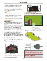
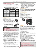
- Install virtual wire with pegs 1 meter apart. It’s 


best to use smooth radius corners than sharp 

- Bury virtual wire below grass and fasten it on 


that the mower should

the ground with pegs, so 


 not cut the wire. 

virtual wire

Add pegs in order to pull the
virtual wire down to the ground 
surface, below the grass tips.

OK

IMPORTANT


INFORMATION

Hard or dry ground may cause pegs to break when

 driving them in. In extreme cases, watering the lawn

ways:

   the first few weeks of operation.

   remainder is buried.

 where the pegs will be driven.

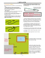
- A minimum distances between the front of the charging

  station and an 

And make sure the 

obstacle is 2 meters. 


 least 

distance from corner to front of charging station is at

 2.5 meters. Make sure to lay a 2.5 meters minimum 

- If a high obstacle, for example a house, wall, fence or 

   other obstacle which is higher than the cutting lawn  


prevent mower 

 at least 35cm from the obstacle. This will 


virtual wire in front of charging station.

straight-light of 


the virtual wire should be laid 

borders the working area, 


with the obstacle.

from colliding 


- If a passage or a ground with same height of cutting lawn, 
the virtual wire should be laid at least 10cm from the edge. 

- A minimum distance between the pool edge of virtual 

wire is 35cm.

- A maximum distance of the virtual wire
to and from the island is 1cm, and fix the  

- There are two types of set up of the 

virtual wire around the charging station. 

1. Put the charging station near corner. 

please take location 1 for reference. 

2. Put the charging station in middle of 
wire, please take location 2 for reference. 

Please make sure to set a straight-line  
at least of 2.5m in front of charging 
station. The charging station should be 
far away from puddle. 

- 7 -

two wires with one peg.  


. See pictures,

angles

- A minimum distance between two corners is 1meter. 

10cm

Passage or  
a ground with 
same level 
of the lawn.

Min:35cm

15cm

House

wall, fence or


other


obstacle


higher 

than the lawn

Location 1.

120

Pool

Max:1cm

Min:35CM

Straight-line
at least:2.5m

Location 2.

15cm

Summary of Contents for TC-158N

Page 1: ...USER MANUAL Please read this manual carefully before use Please keep this manual for future reference ROHS ...

Page 2: ...CONTENTS 1 INTRODUCTION AND SAFETY 1 2 PRESENTATION 3 3 INSTALLATION 6 4 CONTROL PANEL AND REMOTE CONTROL 10 5 USE 11 6 MAINTENANCE AND STORAGE 15 7 TROUBLE SHOOTING 16 8 EXPLODED VIEW 18 ...

Page 3: ...ody 3 Specifications symbol Pasted on mower Pasted on charging station Waste electrical products should not be disposed waste Please recycle where of as household Authority or facilities exist Check with your Local ADDRESS XX Enter XX to mower in order to match the communication between charging station and robot lawn mower S N XXXX XX XX XXX year month date number retailer for recycling advice of...

Page 4: ...tempt to disable or defeat any safety feature is in operation from behind or around the mower and a safe distance manual operation on slopes where degrees or use it in Do not operate the mower if any safety feature or or device Use heavy gloves when inspecting or servicing the Wear eye protection and use gloves when installing driving the wire stakes pegs Firmly the virtual wire and wire from beco...

Page 5: ...stacles Stakes 4pcs Used to fix the charging station to the ground 24 25 26 Remote control battery 2pcs Remote control 1pc Control panel and LCD display For recharging Hole for stake Blade for replacement 2pcs Inner hexagon spanner 1pc 27 Keys 2pcs 28 13 Front wheel 14 Blade Consumable parts 1 Blade 2 Virtual wire 3 Virtual wire connectors 4 Pegs 5 Stakes 6 Remote control battery 7 Inner hexagon s...

Page 6: ...ithout a charging station release it Two cutting modes There are two cutting modes of the mower go straight efficiency and go circle high In Auto mower selects cutting mode intelligently It goes straight if the grass is sparse or it has be cut off long and it goes circle if the grass is dense or In manual mode the mower will just go were you direct it use 100m 600m of virtual wire The wire we sugg...

Page 7: ...rea per hour than if the garden consists of several small lawns separated by 600m 0 5mm 100m 0 5mm Virtual wire maximum length Standard virtual wire length 45 38 5 23 5cm LWH Charging station size Charging station and virtual wire 2 4 Working route Follow virtual wire walking is optional Pressure sensor Rain sensor Auto recharge Intelligent spiraling Go straight Anti theft Lift sensor Tilt sensor ...

Page 8: ... chapter 2 Presentation the installation carefully to plan may restrict the age of the operator of striking it off slopes is greater especially the objects less than 6cm height Please fill up small holes and even out small mounds to make sure lawn is flat How to adjust the cutting height Cutting height explanation take 3cm level for example 3 3 Charging station installation Choose best installatio...

Page 9: ...nt of charging station is at 2 5 meters Make sure to lay a 2 5 meters minimum If a high obstacle for example a house wall fence or other obstacle which is higher than the cutting lawn prevent mower at least 35cm from the obstacle This will virtual wire in front of charging station straight light of the virtual wire should be laid borders the working area with the obstacle from colliding If a passa...

Page 10: ...should be 2 meters at least A maximum distance between the wire and tree root is 20cm Joining the virtual wire If the virtual wire is not long enough and needs to be spliced Use supplied wire connector It is waterproof and gives a reliable electrical connection To splice Insert both cable ends in the connector Now press down the button on top of the connector fully Use a pair of pliers or the like...

Page 11: ...arging station A failed connecting between virtual wire and charging station cause a blinking red light and send out a beeping from charging station 3 Charging light on station in green Non recharging charging light on station in red recharging 3 7 Recharge Recharge Voltage 24V Recharge current 2A 1 When the display shows picture to the right the robot is going to find virtual wire and follow it b...

Page 12: ... or working it goes back to charging station Speed down 1 2 3 4 5 6 7 Turn right Turn left 8 9 10 Enter MANUAL pattern Enter AUTO pattern Battery location with 2pcs AAA battery 11 IMPORTANT INFORMATION Remove the 2 batteries from remote control while it A B C D E F G H I J K A Rain sensor symbol B Working schedule symbol C D E F G Time setting Function setting H I J K 3 1 2 3 4 5 8 9 3 10 7 6 11 i...

Page 13: ...on the key switch 3 Input Password Initial password 0000 the robot enters on standby mode 5 2 Starting the mower preserve balance IMPORTANT INFORMATION charging station is in Green light on Periodically inspect the lawn is without any small hole or mound User can not start the mower if virtual wire or charging station is not in good connecting There are two locations of start the mower 1 Put the m...

Page 14: ... 1 000 MIN AREA 2 000 MIN AREA 3 000 MIN SAVE DEL EXIT AUTO Enter the AUTO mode YES NO SET PASSWORD EXIT ADDRESS INITIAL LANGUAGE AREA RAIN LINE OLD PASSWORD NEW PASSWORD SWITCH SAVE EXIT ON OFF SET ADDRESS Initial now YES NO English French German Danish Swedish Spanish Italian AREA 1 AREA 2 AREA 3 START EXIT Set Rain Sensor ON OFF Set LINESENSOR ON OFF EXIT 12 ...

Page 15: ...TANT INFORMATION By using SCHEDULE function the LINE must be turn on or the robot must be put onto virtual wire Otherwise the robot don t works under schedule time setting 5 7 Password setting 1 Select SET and enter it by pressing key Press key or key to scroll to OLD PASSWORD press key to enter it 2 Select PASSWORD and enter it by pressing key 4 To input OLD PASSWORD Press key or key to scroll to...

Page 16: ...age of mower more than 27V Put the robot back to charging station and wait for working 5 12 Rain 1 Select SET and enter it by pressing key 2 Select RAIN and enter it by pressing key 3 Select YES NO and confirm the selection by key pressing RAIN ON mower goes back to charging station when it is raining RAIN OFF mower goes on working when it is raining 5 14 LINE 1 Select SET and enter it by pressing...

Page 17: ...e so not to damage surfaces and the plastic components the varnished Every months 3 Robot Carry out for rechage See Battery when intervening on the blade the electric and the electronic components battery agent seek medical help if it comes water neutralising etc into contact with the eyes 15 Servicing of the mower should be according manufacturers instructions This product to must be disposed of ...

Page 18: ...t the mower still can not start Mower stops working and beeping 1 Mower is lifted from ground 2 Someone or object ride or sit on the mower 1 Take the mower on level ground and restart it 2 Take the object away from mower and restart it Mower stops working and beeping 1 Running wheel strike 1 Cutting height is too low 2 Blade strikes hard objects 3 Mower is trapped in lawn 1 Adjust the cutting heig...

Page 19: ...ging station in a flat place Confirm the ground before the charging station is leveled with the station if necessary fill area with dirt Relocate the virtual wire 1 Replace a new blade 2 Stop the mower in safety use protection gloves to avoid the risk of cuts on hands remove the fold cause from blade 3 Start the robot in new place 1 Damaged cutting blade 2 Cutting blade flooded by residues tapes r...

Page 20: ...sor Emergency switch Cutting motor Blade head Blade Running motor cover Running motor Running motor gear Bearing pressure plate Wheel gear Bearing Wheel axle Rear wheel Wheel shell Bottom base Lift sensor No Sparepart Name Screw cap Gasket Front wheel Spring sheet Bump switch Main PCB Front bumper Charging head Side bumper 24 25 26 27 28 29 30 31 32 33 34 35 Oil seal Charging terminal Copper sleev...

Page 21: ...1 Top cover 2 PCB Charging Station Exploded View 3 Power terminal 4 Virtual wire terminal 5 Underpan 6 Copper sheet 8 EXPLODED VIEW 19 1 2 3 4 5 6 7 7 Copper sheet permanent seat ...

Page 22: ...USER MANUAL Robot lawn mower ...

Reviews: