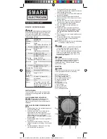

DIODE MEASUREMENT
Test the voltage drop in diodes.
1. Turn the Range Selector Switch to the Diode
( ) position.
2. Plug the red Test Lead into the V
Ω
mA (Center)
Jack. Plug the black Test Lead into the Com
(Bottom) Jack. Switch the Multimeter ON.
3. Connect the red probe to the anode of the diode
and the black to the cathode.
4. The approximate forward voltage drop of the
diode will be displayed in mV. If the connection
is reversed only “1” will be shown.
BATTERY CHARGE MEASUREMENT
Test the amount of charge left in batteries.
!
!
WARNING
This setting is for testing the charge of small 9V or
1.5V batteries only. Never use this setting to test
automotive or lead-acid batteries. The high current
could cause damage to the meter and/or cause
severe personal injury. Use the appropriate DC
Voltage setting to test the open current voltage of
such batteries instead.
1. Turn the Range Selector Switch to the Battery
( ) position.
2. Plug the red Test Lead into the V
Ω
mA (Center)
Jack. Plug the black Test Lead into the Com
(Bottom) Jack. Switch the Multimeter ON.
3. Connect the red probe to the positive terminal
of the battery and the black to the negative
terminal.
4. The battery amperage under a load of 370 m
Ω
will be displayed to a resolution of .1mA.
5. Normal amperage:
For a standard 9V (6LR61) battery = 25 mA
For a 1.5 V “AA” (LR6) battery = 4 mA
MAINTENANCE
1. Wipe unit with a slightly damp cloth using
a light detergent. Do not use solvents or
abrasives.
2. Remove battery if not in use for long periods.
3. Store unit in a dry location.
4. Other than the battery and fuse, there are no
replacement parts on this unit. Repairs should
be done by a qualified technician.
BATTERY/FUSE REPLACEMENT
To replace the battery or fuse:
1. Remove the Test Leads from the multimeter.
2. Turn the unit over.
3. Remove both screws using a Philips
screwdriver.
4. Remove back cover.
5. Pull battery/fuse out of unit and replace with the
same. (9V battery or 500mA/250V fast-acting
fuse)
6. Replace cover and retighten screws.
© 2010 Distributed by
Menard, Inc.
Eau Claire, WI 54703
GAR_TL_013_0410
Made in China
ADDITIONAL MULTIMETER PRECAUTIONS
1. Do not test voltage on AC circuits higher than
750 volts.
2. Do not test voltage on DC circuits higher than
1000 volts.
3. Do not test current on circuits higher than 10
amps.
4. Be careful not to apply voltage to the Test Leads
when they are connected to the COM (Bottom)
and V
Ω
mA (Center) Jacks and the Multimeter is
in an Ohms testing setting. Damage can occur
to the multimeter or the fuse may blow.
5. Do no switch between testing modes with the
multimeter connected to a circuit.
AC VOLTAGE MEASUREMENTS
Measure AC conductors carrying up to 750 VAC,
45-450 Hz.
1. Turn the Range Selector Switch to 750 ACV
setting. Always start with the highest range if
the voltage is unknown.
2. Plug the red lead into the V
Ω
mA (Center) Jack.
Plug the black lead into the COM (Bottom) Jack.
Switch the Multimeter ON.
3. Carefully touch the exposed conductors with the
tips of the probes to measure the voltage (not
amperes).
4. Read measurement. If the voltage is less than
200 volts, set the Range Selector Switch to the
lower range.
5. When testing is complete, remove Test Leads
and store with multimeter.
DC VOLTAGE MEASUREMENT
Measure DC conductors carrying up to 1000 VDC.
1. Turn the Range Selector Switch to 1000 DCV
setting.
2. Follow the directions above under “AC Voltage
Measurements”, only use the DC setting
instead.
DC CURRENT MEASUREMENT
Measure DC conductors carrying up to 10 amperes.
1. Turn the Range Selector Switch to the 10A
position. Always start with the highest range if
the amperage is unknown.
2. Plug the red lead into the 10A (Top) Jack. Plug
the black lead into the COM (Bottom) Jack.
Switch the Multimeter ON.
3. Carefully touch the exposed conductors with the
tips of the probes to measure the amperage.
NOTE: Amperage is always tested in series with
the circuit under test.
4. Read measurement. If the reading is less than
.2 AMPs, switch the red lead to the V
Ω
mA
(Center) Jack and set the Range Selector Switch
to the 200mA setting.
5. When testing is complete, remove Test Leads
and store with multimeter.
RESISTANCE MEASUREMENTS
Measure circuit resistance up to 2000K Ohms.
!
!
WARNING
NEVER measure resistance on a circuit with voltage
running through it.
1. Turn the Range Selector Switch to the 200
Ω
position.
2. Plug the red Test Lead into the V
Ω
mA (Center)
Jack. Plug the black Test Lead into the Com
(Bottom) Jack. Switch the Multimeter ON. Short
the Test Leads together. The meter should read
“0” Ohms.
3. Touch the exposed conductors with the tips of
the Test Leads.
4. Read measurement. If the reading is “1”, set the
Range Selector Switch to the next higher Ohm
(
Ω
) position.
TRANSISTOR (HFE) MEASUREMENTS
Test transistors to ensure proper function.
1. Turn the Range Selector Switch to the hFE
position. Switch the Multimeter ON.
2. Insert the transistor pins into the appropriate
hFE jack (NPN or PNP) according to the EBC
(Emitter, Base, Collector) sequence.
3. The meter will show the approximate hFE value.
GAR_TL_013_0410_Smart_Electrician_Ins_Manual_364-5017_Digital_Multimeter.indd 2
4/21/10 10:44 AM


