background image

Installation and Operation 

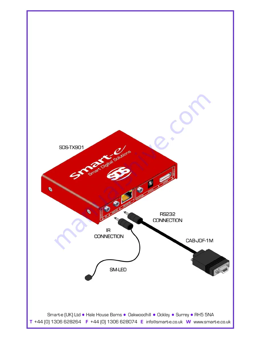
3.   Connecting Infra-red and RS232 to the transmitter 


3.1 

The Infra-red is accessed via a 3.5mm mono jack on the left hand side 


of the rear panel. Using the appropriate interconnecting device (SM-


LED) connect the jack end to the SDS-TX901 and stick the other end to 


the AV device you want to control, making sure the emitter is placed 


close to the IR receiver in the AV device. 


Note: the pin connections of the SM-LED are an industry standard so 


other manufactures should be compatible 


3.2 

If  using  RS232  connect  control  cable  to  the  mini-jack  input  as  shown 


in the diagram below, using a CAB-JDF-1M 


-

5-


Summary of Contents for SDS-901

Page 1: ......

Page 2: ...ility and fitness for particular purpose Smart e will not be liable for errors contained inside this manual or for incidental or consequential damages in connection with the furnishing performance or...

Page 3: ...utions SDS What s in the box 1 What is the SDS 901 2 Why is the SDS 901 necessary 2 How does the SDS 901 work 2 Installation and Operation Transmitter 3 Receiver 8 Appendix Specifications 11 Limited w...

Page 4: ...listed below are missing please contact the Smart e dealer you purchased products from or contact Smart e customer support at 44 0 1306 628264 If you ordered a SmartLynx Set Item Description SLX 900...

Page 5: ...8 UTP cable over distances of up to 100m The actual distance is a func tion of cable type see below How does the SDS 901 work The Smart e SDS 901 is a transmitter and receiver pair designed to extend...

Page 6: ...d by connecting the devices directly to the computer and checking that the devices operate as desired without the SDS 901 system Potential System Set up Install CAT 5 wiring between desired locations...

Page 7: ...he audio input to either an analogue or a TOSlink output of the AV source Select audio type as required by pressing the Audio Select button on the front panel and check the audio status LED on for ana...

Page 8: ...evice SM LED connect the jack end to the SDS TX901 and stick the other end to the AV device you want to control making sure the emitter is placed close to the IR receiver in the AV device Note the pin...

Page 9: ...he audio connector on for analogue off for digital 4 2 The additional audio channel can be accessed through the mini TOSlink connector This connector has a dual function and can accept either a standa...

Page 10: ...coaxial cable due to its low cost and ease of installation This cable is used for LAN applications and is found in abundance already installed in many buildings The category 5 is a standard which est...

Page 11: ...T 5 cable is connected to the transmitter output connect the cable to the RJ45 socket on the receiver unit 7 2 If the cable connection is correct the power all 3 LEDs will illuminate power is sent up...

Page 12: ...nfra Red signals back down the cable to the transmitter unit then connect an eye SM EYEN to the jack position as shown in the diagram below 8 2 If using RS232 connect control cable to the mini jack in...

Page 13: ...to be assembled into a 1U shelf Attachment is via 2 x M3 bushes in the front panel These are fitted for both the transmitter and receiver units 9 2 There are also holes stamped into the lid of both t...

Page 14: ...link Video Output Signal Type Connector HDMI Audio Output Signal Type Analogue stereo or TOSlink Connector Mini TOSlink IR Input Signal Type 30 115kHz modulated IR Connector 3 5mm stereo mini jack soc...

Page 15: ...Any replacement product could be new or like new provided that it has functionality at least equal to that of the product being replaced 6 Smart e warranty is valid in any country where the covered pr...

Page 16: ...X SCX TX550 One to Five Transmitter Unit with RS232 IR SmartCast System TUSC 1042 SmartCast Eurocard Rack Up to 16 cards SCX TX120E Dual Screen Transmitter Eurocard SCX TX550E One to Five Transmitter...

Reviews: