background image

26

The SmartDVR.com

Quality & Value

5-3. CONFIGURATION

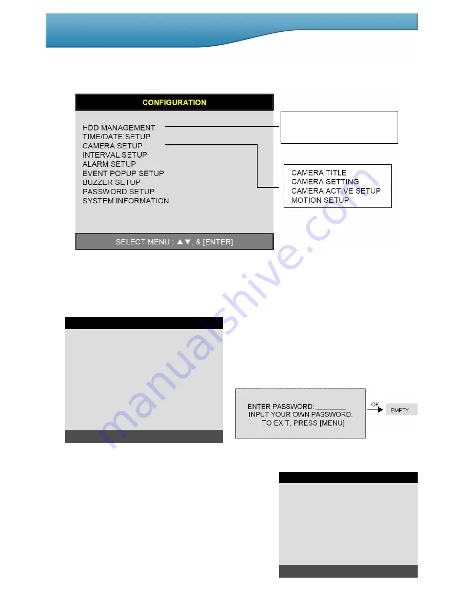
Various system parameters can be set in the CONFIGURATION menu.
Enter the SYSTEM MENU-CONFIGURATION and press the [ENTER] button.

1) HDD MANAGEMENT

Enter SYSTEM MENU-CONFIGURATION-HDD MANAGEMENT and press the [ENTER] button.

(1) HDD SETUP

This page includes information about start and end of recording, location of recorded data, or location of last
playback on HDD. In addition, users can delete all the data on HDD.

On the [HDD CLEAR] sub-menu, press the [ENTER]
button to delete all image data on HDD.

The system will ask you the password for verification. After
you clear all data on the HDD, the status of HDD CLEAR
changes from IN USE to EMPTY.

When you clear HDD, the event list is deleted, too.

   If you selected OVERWRITE in Record Setup, the HDD STATUS above will display OVERWRITE.

(2) HDD INFORMATION

This menu will show the physical state of the HDD in the DVR.

HDD SETUP
HDD INFORMATION
HDD CHANGE SETUP

MASTER-1

MASTER-1

MASTER-1

HDD INFORMATION

[MASTER-1]

MODEL
SPEED
SIZE
START
END

[MASTER-2]

MODEL
SPEED
SIZE
START
END

:                               Maxtor 6Y080L0
:                                                PIO-4
:                    81,964,302,336 BYTES
:                        2005/04/08 12:08:56
:                        2005/04/08 12:08:56

:                                  AT5520026DT
:                                    240/120nsec
:                                                80GB
:                        2005/04/08 12:08:56
:                        2005/04/08 12:08:56

TO EXIT, PRESS [MENU]

HDD SETUP

STATUS           HDD                   DATE/TIME
----------------------------------------------------------------------
BEGIN        MASTER-1                    2005/04/08

12:12:05

RECORD   MASTER-1                     2005/04/09

15:09:58

PLAY         MASTER-1                     2005/04/08

19:44:31

HDD STATUS                                     NORMAL
HDD CLEAR                                          IN USE

HDD CLEAR [ENTER], EXIT [MENU]

Summary of Contents for DSD154

Page 1: ...JPEG2000 H264 USER MANUAL Models covered DSD154 4 Channel DVR DSD158 8 Channel DVR TheSmartDVR com Version 2 0 1 0 ...

Page 2: ...ore initial configuration or operation you must first set the TIME DATE followed by setting the unit to the FACTORY DEFAULT settings lastly clearing the HDD Please follow these steps in order Pull the unit out of record mode prior to cutting off power to the unit Do this by entering the setup menu followed by switching the unit off Powering off the unit while writing to the disks can cause critica...

Page 3: ...ard Disk Drive 11 3 Camera 12 4 Monitor 12 5 Power 12 6 Spot Video Printer 13 7 Other External Device 13 Chap 4 Operation 14 4 0 Start up DVR 14 4 1 System Log in 14 4 2 Factory Default 14 4 3 Display Configuration 15 4 4 Live View Setup 15 1 Full Multiple View 15 2 View in Sequence 16 3 PIP View 16 4 Freeze View 16 5 Zoom View 16 4 5 Record 17 4 6 Playback 17 4 7 Search 18 4 8 PTZ Camera Operatio...

Page 4: ...ord Setup 31 9 System Information 31 5 4 Record Setup 32 1 Record Configuration 32 2 Schedule Setup 33 3 Holiday Setup 33 5 5 Back Up 34 5 6 External Device 35 1 TCP IP Setup 35 2 RS 232C Setup 38 3 Pan Tilt Zoom Setup 38 4 Spot Monitor Setup 40 5 Audio Setup 41 5 7 FACTORY Default 41 5 8 Language Setup 42 CHAP 6 Network Setup 43 CHAP 7 IRS Integrated Remote Station 46 CHAP 8 Programmer Reference ...

Page 5: ... JPEG 2000 compression algorithm No mosaic effect Suitable for recording not only images but also text Forward Playback Speeds X1 16 X1 8 X1 4 X1 2 X2 X4 X16 X32 X64 Backward Playback Speeds X1 16 X1 8 X1 4 X1 2 X2 X4 X16 X32 X64 Easy and convenient search by Jog Shuttle Remote Controller Data Back Up Simple Back Up using built in DVD Writer Back up DVD Player included in the package Network Back ...

Page 6: ...pter 12 V DC power supply to DVR main board 5 User s Manual User s Manual 6 Software CD Remote Viewer Software Back up DVD player 7 Battery Battery for remote controller 8 Bolts Foam Mount Washers For attaching Hard Disk Drive into DVR 9 Mouse PS 2 Mouse 1 DVR Main Unit 2 Remote Controller 3 Power Cable 4 Power Adapter 8 Bolts Foam Mount washers 7 Battery for remote 6 Software CD 5 User s Manual C...

Page 7: ...FF LIGHT OFF CLEAR CLEAR PRESET OPEN IRIS OPEN GOTO GOTO PRESET CLOSE IRIS CLOSE AUTO AUTO SCAN NEAR FOCUS NEAR F1 USER 1 FAR FOCUS FAR F2 USER 2 WIDE ZOOM IN F3 USER 3 4 1 Camera selection 4 2 PTZ camera control TELE ZOOM OUT F4 USER 4 5 SHIFT THIS KEY IS PRESSED TO SELECT ADDITIONAL FUNCTIONS ON A KEY Emergency Record at continuous 60ips SUPER FINE size Press hold for 3 seconds to return to Sche...

Page 8: ...k press Shift K Lock for 3 seconds Switches from full screen display to 9 split screen 14 PTZ 15 SEQ 16 PIP 17 AUDIO 18 ZOOM 19 FRZ 20 K LOCK 21 MODE 22 Q PLAY QUICK PLAY Play images recorded 2 minutes ago in forward direction only if recording in continuous mode Pressing Jog Shuttle button Ready for use Jog Shuttle In playback mode pressing J SHUTTLE button freezes images RUN LED on While you ope...

Page 9: ... the DVR NOTE This facility is not supported 5 CAMERA Input Connection with camera 6 LOOP Output Camera loop out 7 MONITOR Output Connection with Composite Video Monitor 8 SPOT Connection with additional Composite Video Monitor 9 DC Power DC power input DC12V 6 67A adapter 10 POWER SWITCH Power ON OFF NOTE To avoid deletion of HDD data make sure you press MENU button and enter into menu setup befo...

Page 10: ...10 The SmartDVR com Quality Value CHAP 3 Installation 3 1 Installation Configuration ...

Page 11: ...rder MASTER Screw hole MAIN BOA I O BOARD x x x x x x x x x x x x 1 Connect Main Board and HDD1 using IDE cable and HDD power cable 2 When you use just 1 HDD install the HDD onto HDD1 location 3 When you use 2 HDDs install the first HDD onto HDD1 location and then install the second HDD onto HDD2 location in order 4 Stick the HDD absorber included in package on the bottom of case and then install ...

Page 12: ...OR to Video In of Main monitor 5 Power CHAP 3 Installation Connect one 12V DC 6 67A adaptor to the DC12V input connector on rear of unit NOTE Before you turn on power switch ensure that power adaptor cameras and monitor are connected properly ALSO TO AVOID DELETION OF HDD DATA ENSURE YOU PRESS MENU AND ENTER BEFORE POWERING DOWN THIS TAKES UNIT OUT OF RECORD MODE ...

Page 13: ...or CRT TFT LCD Select VGA in DISPLAY SETUP menu before connection to VGA monitor Resolution set by manufacturer is 800x600 60Hz This can be altered by entering Monitor Setup VGA Setup VGA resolution Use VGA option board for both CRT type PC monitor or TFT LCD monitor AUDIO INPUT Microphone Input IN1 IN4 AUDIO OUTPUT Speaker Output OUT CHAP 3 Installation PTZ C AMER A PC SENSOR SIRE N PAN TILT CAME...

Page 14: ...ust press MENU button followed by the ENTER button Factory default password ADMIN Blank MANAGER 1 USER 1 USER 8 2 9 We recommend configuring a unique password as per the procedure in SYSTEM MENU CONFIGURATION PASSWORD SETUP For security reasons be sure to make note of your own password 4 2 Factory Default Before initial configuring or operation you must first set the Time Date followed by setting ...

Page 15: ... displays by pressing MODE For full image display just press the channel button you want or keep pressing MODE button When you playback images that are recorded in 360x240 360x288 or 360x120 360x144 resolution only 1 4 and 9 way split screens are available Full Screen FULL SCREEN During Playback Full Screen 360x240 360x120 ...

Page 16: ...Z icon will be activated on screen and the F character will be shown beside camera title and the live image will be frozen Split display mode If you press the FRZ button the FRZ icon will be activated on screen Then press the channel button you want to freeze To release frozen image press channel number of frozen image again and press FRZ button to exit FRZ mode 5 Zoom View In full screen press th...

Page 17: ...d in the following conditions While entered in the menu No camera connected HDD is full and Overwriting is off in the Record Setup menu 4 6 Playback In record mode or stop mode press PLAY button to play the recorded data in 1x speed Press LEFT for backward playback or press RIGHT button for forward playback Use Jog Shuttle to pause and control playback speed To stop playback press the PLAY button ...

Page 18: ...ttle It starts from image corresponding to set of data on the search bar 2 TIME DATE Search by time date Playback starts from the time date selected 3 EVENT LIST Search by event list Motion Alarm Video Loss 4 8 PAN TILT ZOOM Camera Operation Press PTZ button first for PTZ control mode Numeric buttons from 1 to 16 and direction buttons are assigned for each PTZ command and user can control PTZ came...

Page 19: ...lly as per start time date and the back up data size you set User can select the back up data size size of back up data from start of back up on SIZE item but END of back up time is automatically determined by DVR system 3 Press ENTER button on BURN sub menu DVR system starts burning CD or DVD 4 When burning is completed CD R or DVD R media will eject automatically If you wish to continue backup o...

Page 20: ... on the place of Mouse it shows Width Length and BOT Click hold WHEEL button Deletes MOUSE ICON Click Hold LEFT button In ZOOM mode holding this button will change the icon If User moves the MOUSE ZOOM area also moves 3 Working Status in SETUP MENU LEFT button click once ENTER LEFT button double click NEXT LEFT button click hold MINUS WHEEL button click once MODE Schedule Recording MASK SETUP WHEE...

Page 21: ...utton click once Following is the assigned KEY by each ICON ICON Left Click Right Click ICON Left Click Right Click MENU NEXT ENTER PLUS MINUS MODE REC STOP PLAY QPLAY SEARCH PTZ ZOOM FRZ PIP SEQ AUDIO KLOCK 5 Working Status of PLAY MOUSE ICON Mouse works the same as the above LIVE ICON Place mouse on ICON and by Wheel Up Down button PLAY SPEED can be controlled Pause mode place mouse on ICON and ...

Page 22: ...WHEEL LEFTUP UP RIGHTUP LEFT ENTER RIGHT LEFTDOWN DOWN Change Channel RIGHTDOWN Change Channel ZOOM IN OUT ZOOM IN OUT FOCUS NEAR FAR FOCUS FAR NEAR GOTO PRESET Change Channel SET PRESET PLUS MINUS PRESET NUM CLEAR PRESET AUTO SCAN Change Channel PTZ MENU EXIT Change Channel MENU NEXT Change Command 6 Working Status of PTZ MOUSE ICON Mouse works the same as the LIVE ICON Place Mouse on ICON and us...

Page 23: ...on click left button of mouse once Please note that specific division cannot be supported such as QUAD record playback and according to DVR channel screen division can be different 1 4 8 6 9 8 Working Status of NUMBER MOUSE ICON User can use it for KLOCK or LOGIN and change PASSWORD 1 2 3 4 5 6 7 8 9 10 ...

Page 24: ...y PLUS Increase the option value SHIFT key Jog Left turning Move backward to next image Decrease value Jog Right turning Move forward to next image Increase value Jog Shuttle Shuttle left turning Reduce playback speed Decrease value Shuttle right turning Increase playback speed Increase value SYSTEM MENU TCP IP SETUP RS 232C SETUP PAN TILT SETUP SPOT MONITOR SETUP AUDIO SETUP AUDIO VOLUME SETUP RE...

Page 25: ...r Not available with VGA option NOTICE When this DVR unit is operated for the first time it will take a few seconds to boot up for initialisation of VGA mode 4 3 Select the sub menu that you would like to set using direction buttons and then change ON OFF with ENTER button 1 TIME DATE Display time date 2 DVR STATUS Display system setting status 3 ICON DISPLAY Display function setting status 4 REC ...

Page 26: ...s menu will show the physical state of the HDD in the DVR HDD SETUP HDD INFORMATION HDD CHANGE SETUP MASTER 1 MASTER 1 MASTER 1 HDD INFORMATION MASTER 1 MODEL SPEED SIZE START END MASTER 2 MODEL SPEED SIZE START END Maxtor 6Y080L0 PIO 4 81 964 302 336 BYTES 2005 04 08 12 08 56 2005 04 08 12 08 56 AT5520026DT 240 120nsec 80GB 2005 04 08 12 08 56 2005 04 08 12 08 56 TO EXIT PRESS MENU HDD INFORMATIO...

Page 27: ... power off the DVR and change with new HDD NOTICE Be sure to write down the DVR information such as NTSC PAL MODEL name Channel HDD location PORT 1 PORT2 When you want to retrieve the HDD old you must do this based on this DVR information 2 LOAD DVR INFO LOAD DVR INFO it retrieves recorded HDD from other DVR set HDD retrieval procedure 1 Install HDD with new DVR and power on 2 Press STOP button wh...

Page 28: ...ing using UP DOWN button and adjust using button or Jog shuttle CHANNEL Select camera BRIGHTNESS Adjust image brightness 32 31 CONTRAST Adjust colour contrast 32 31 SATURATION Adjust colour saturation 32 31 HUE Adjust colour hue 32 31 CAMERA POSITION Adjust camera image to the center If value is lower Left value is higher Right 0 80 CAMERA TITLE SETUP 0123456789 ABCDEFGHIJKLMNOPQ RSTUVWXYZ CAMERA0...

Page 29: ... area Direction button is for moving ENTER button is for selection and MODE button is for changing mode of MASK SETUP CELL Move to the location that you want to detect and then press the ENTER button Highlighted cell area means motion detection area ALL ON Set all cells as detection area Use ENTER button to set ALL OFF Set all cells as no detection area Use ENTER button to set BLOCK ON Select dete...

Page 30: ...al Open type and N C Normal Close type ALARM INPUT Select type of alarm sensor connected to DVR Unit N O or N C Use direction buttons or to set DISABLE disables alarm sensor connected to DVR DURATION Set the duration of alarm when an alarm is Activated 0 seconds 300 seconds 6 EVENT POPUP SETUP When event is activated a full screen image will popup CHANNEL Select a channel that uses an event motion...

Page 31: ...Then input again the new password to confirm Default value ADMIN NULL MANAGER 1 USER 1 2 USER 8 9 Change the user PASSWORD during the first operation is recommended Ensure that you record the new password 9 SYSTEM INFORMATION DVR system information including firmware version hardware version product ID etc CHAP 5 Set Up BUZZER SETUP ALL KEY BEEP VIDEO LOSS ALARM ACTIVE MOTION DETECT ON ON ON OFF S...

Page 32: ... or Enhanced and record at 360x288 PAL 4 RESOLUTION Set recording resolution in PAL mode 50 ips at 720x288 PAL 60 ips at 720x240 NTSC 100 ips at 360x288 PAL 120 ips at 360x240 NTSC 200 ips at 360x144 PAL 240 ips at 360x120 NTSC Images recorded in 360x288 It is not possible to see those images in full screen mode in playback Recording in half or quad resolution is recommended for higher recording s...

Page 33: ...abled the DVR system records according to the SCHEDULE Record Setup The DEFAULT record mode set by the manufacturer is C which is CONTINUOUS recording mode RECORD TYPE After power on Schedule record Exit from menu Schedule record Press and HOLD E REC Emergency Record Schedule record End of search or playback Schedule record After pressing E REC Emergency record Emergency record Continuous recordin...

Page 34: ...d then select BURN DVR system starts copying images to CD DVD and displays following message CD RW BURNING START CD RW BURNING LEAD IN CD RW BURNING IMAGE DATA CD RW BURNING CLOSE TRACK CD RW DOOR OPEN When burning is complete CD R DVD R media will eject automatically To copy more images repeat above process In next process START time in CD R sub menu shall be END time in previous back up and you ...

Page 35: ...G HDD START 2005 AUG 07 AM04 04 12 END 2005 AUG 08 PM08 12 23 USB MEDIA START 2005 AUG 07 AM04 04 12 END 2005 AUG 08 PM08 12 23 SIZE 28 MB 28MB BACKUP START WRITING IN USB STORAGE Status message EXIT MENU EXIT MENU System Status Messages 1 If MEMORY STICK is not inserted USB STORAGE IS CHECKING USB STORAGE IS NOT AVAILABLE RE CONNECT THE USB STORAGE CONECT THE OTHER USB STORAGE 2 When MEMORY STICK...

Page 36: ...e properly to successfully access to DVMR unit via Internet line If data transmission speed is high enough leave TIMEOUT value as set by manufacturer 200 msec and increase it if data ansmission via Internet line is relatively slow Execute tracert Tracing Route in your PC for IP assigned to DVMR unit and you can figure out how much TIMEOUT value increased RETRY COUNT Set the retry number of times f...

Page 37: ...GMT TYPE GMT 00 00 SELECT CHANGE VALUE EVENT SERVER SETUP IP ADDRESS 192 168 001 072 IP PORT 09988 EVENT SERVER TYPE OFF INTERVAL EVENT GMT TYPE GMT 00 00 SELECT CHANGE VALUE 6 NVS SETUP BITRATE DATA SIZE from NVS The bigger it set the better its quality but sometimes motion is not smooth Set Value 100K 2500K can be adjusted by 50K GROUP OF PICTURES Image I frame P frame from NVS The bigger it set...

Page 38: ... PAN TILT SETUP The DVR is capable of operating PTZ control via a number of protocols PELCO D DRX502A HID2404 AECD 2000 VIDO AU GXX SCC 641 HMC 250 ACCUDOME PELCO P YOKO ON D DCS 230S TBT D MAX LG MULTIX MERIT LI LN SU320 SENSORMATIC M CONTROL NOVUS C1 NOVUS C2 NEOTECH A To access the PTZ set up screen first enter SYSTEM MENU then EXTERNAL DEVICE menu followed by the PAN TILT SET UP COMMAND SETTIN...

Page 39: ...d side of screen This displays current function Setting up PTZ presets using front panel 1 Once on PTZ screen press 11 GOTO button 2 Select required preset number using inner jog wheel 3 Press 10 CLEAR to clear previous preset 4 Using curser keys move camera to desired position 5 Press 9 SET button Warning Do not press 9 SET unless a clear unused preset has previously been selected using the 11 GO...

Page 40: ...oyed Calling Dome Tours etc will depend on the preset code allocated to the specific dome eg PTZ300 51preset Refer to cameras manual for further guidance 4 SPOT MONITOR SETUP 5 AUDIO SETUP Use direction button to move to channel and press ENTER button to set ON OFF 1 SWITCHING INTERVAL Channel switching time 1 sec 99 secs 2 ALARM POP UP Set ON to show screen pop up on Alarm 3 MOTION POP UP Set ON ...

Page 41: ...UME Adjust VOLUME of Recorded AUDIO LIVE VOLUME1 4 Adjust VOLUME of LIVE per channel PLAY VOLUME1 4 Adjust VOLUME of PLAY per channel AUDIO VOLUME SETUP INPUT VOLUME 32 LIVE VOLUME1 32 LIVE VOLUME2 32 LIVE VOLUME3 32 LIVE VOLUME4 32 PLAY VOLUME1 32 PLAY VOLUME2 32 PLAY VOLUME3 32 PLAY VOLUME4 32 SELECT CHANGE VALUE AUDIO VOLUME SETUP INPUT VOLUME 32 LIVE VOLUME1 32 LIVE VOLUME2 32 LIVE VOLUME3 32 ...

Page 42: ...42 The SmartDVR com Quality Value 5 8 LANGUAGE SETUP The menu can be displayed in a number of languages Press ENTER button to select language ...

Page 43: ...t access after installing any new equipment routers switches modems etc If possible use a PC on the network to verify that an Internet connection can be made and that all current configurations on any equipment are up and working properly Do this before doing ANY configurations with the DVR We are assuming that your current equipment is configured properly for Internet access PC s TCP IP Setting B...

Page 44: ...2 168 001 105 1 Enter the DVR Menu Go to EXTERNAL DEVICE Go to TCP IP SETUP 2 Enter IP CONFIG SETUP 3 SET IP ADDRESS see above IP PORT 50000 GATEWAY 192 168 1 1 example Router base address SUBNET MASK 255 255 255 000 example Assign the DVR the same exact subnet mask as your PC 4 Please DO NOT configure MAC ADDRESS but set DHCP SETUP to MANUAL 5 EXIT MENU 6 Now turn Router off and on This will take...

Page 45: ...ternet Service Provider Customers using a dynamic I P address on their Broadband connection are advised to source a modem router supporting Dynamic DNS within its firmware and to refer to the instructions provided with that router in order to configure that service ...

Page 46: ...lay BACKUP Enables to back up recorded images in DVR to your PC PLAYER Enables to back up recorded images on your PC AJP file TRANSMITER Enables to control DVR using virtual key like controlling actual DVR remotely CLIENT Enables to control LIVE PTZ control Playback in DVR remotely CMS Enables to have multi access for showing live images of many DVRs Additionally enables to search and show recorde...

Page 47: ...dress and port number that you already registered in DDNS Server MEMBER ID Input member ID that you registered in DDNS Server NAME Input DVR name that you registered in DDNS Server ADDRESS Input IP address manually PORT Input Port number manually LOGIN ID Input DVR ID which has been set in DVR already Input admin Password Input password of DVR ...

Page 48: ...rm Buzzer Interval Password Record Configuration Record Schedule MANUAL Input IP address and port number of DVR manually ADDRESS Input IP address of DVR manually PORT NUMBER Input port number of DVR manually LOGIN ID Input DVR ID which has been set in DVR already Input admin PASSWORD Input password of DVR CLOSE Click CLOSE to exit ...

Page 49: ...see live view over a network b DISCONNECT Click this button to disconnect 3 System Information Displays connection status and operating Information 4 PTZ Control Command PTZ Camera connected to DVR remotely To command PTZ remotely User must complete PTZ setting in DVR 5 Channel button Selects ch that displays in full screen 6 Screen division User can select screen division 1 2 3 4 5 6 ...

Page 50: ...Quality Value 7 4 BACKUP 1 To execute BACKUP input IP Address Port and click Connect Test button 2 After Connect Test is done you can see Success Connect Test message Then click lock button and click Set Backup Time button ...

Page 51: ...R com Quality Value 3 Now you set Start Time End Time Save File Path File Size and click Apply 4 After finishing time setting click Start Backup to start backup Then you can see the backup on the path that you chose ...

Page 52: ...ve and print d AVI SAVE Save backup images in AVI file format c EXIT Ends backup player 6 Operation buttons Search for recorded data a Go to the beginning of recorded data and play b Fast backward playback c Backward playback d Pause e Forward playback f Fast forward playback g Go to the end of recorded data and play 7 Playback speed setting button Able to adjust playback spped by using upper lowe...

Page 53: ...er and dark part of image darker To reduce light and shade lower contrast a little Brightness make an image brighter make an image darker Sharpness gives sharp edge effect Blur make an image soft Operation buttons saves data in JPEG file format It is saved in the folder where player is installed User can print current image selected 2 EDIT Return to player mode ...

Page 54: ...cides frames per second of data to be saved SIZE Decides the size of data to be saved automatically START Starts saving STOP Stops saving Once stopped C WEB_BACKUP folder is opened automatically 2 AVI SAVE Opens option setting to start AVI saving Closes option setting after finishing AVI saving and go back to player mode 1 2 ...

Page 55: ... or set NVS Setup of DVR System Menu 3 System Information Displays DVR Connection and System Operation Information 4 PTZ Control User can control PTZ camera connected to DVR remotely To control PTZ remotely user must set PTZ setting in DVR in advance 5 DVR Virtual Key To use Virtual Key that works the same function as DVR to control DVR remotely a Bitrate shows received data from network Please re...

Page 56: ...GOP Image I frame P frame from NVS The bigger it set the better its quality Frame Rate DATA RATE from NVS The bigger it set the better its movement But sometimes image is not smooth Resolution DATA RESOLUTION from NVS Such as 160 120 320 240 640 480 In order to work NVS properly above value should be adjusted according to Network Condition Please refer to bitrate displayed in TRANSMITTER when user...

Page 57: ...the controls for the PTZ please press and hold the button for 1 2 seconds per instance to compensate for the data transmission rate If you do not and instead simply click the PTZ buttons you may get undesired results c The plus and minus buttons send the PTZ commands to the corresponding PTZ camera ID 5 Channel number button Select the channel that you want to view based on what Screen Division vi...

Page 58: ... vendor Name Name of IP address on the list Address Input IP address which is set on DVR PORT Input PORT which is set on DVR ID Input ID which is set on DVR Please input admin Password Input password which is set on DVR IP List It shows IP list which user input manually Select Button Select IP and PORT on the list Save Button Save IP and PORT on the list Delete Button Delete IP and PORT on the lis...

Page 59: ... Scan Rate Set speed of playback PTZ TYPE Select PTZ camera which is connected to DVR PTZ Baud Rate Enter the Baud Rate of your PTZ camera Set Path to Save Downloaded image Determines the location and folder on your PC where the downloaded video clips are stored Run in full screen mode When checked this will enable the program to re adjust the interface to completely fill your computer screen ...

Page 60: ...e DVR View Tree If No11 is not displayed it will be displayed again View Event If No 12 13 is not displayed it will be displayed again Exit Exit from CMS Screen Division Set number of channels displayed in CMS Rotation Sequence images Auto Rotation Automatic image sequence In CMS Setup adjust Auto Change Value PTZ Control PTZ control DVR Information Displays multi access DVR camera at Site or Grou...

Page 61: ...ect DVR from main screen select CMS Setting Site setup Registering Site and then register necessary information for DVR connection as below Registration is the same as IRS SETUP 2 After registration user can display specific channel or select whole site by dragging Mouse as below ...

Page 62: ...VR Group Setup 1 After finishing DVR registration click Group Setup in Main Screen 2 Click Add Group and input group name Drag camera channel user wants as shown below and set channel displays in Group and click Save Array to setup group ...

Page 63: ... F QPLAY Y CH7 7 CH14 PAUSE A NEXT N MODE D CH1 1 CH8 8 CH15 Search E ENTER 0x0d PIP I CH2 2 CH9 9 CH16 MENU M SEQ Q CH3 3 CH10 0 UP U J SHU L CH4 4 CH11 Jog Shuttle When ACTIVE LED is on Jog Shuttle is ready to be activated by the commands below Shuttle 0 degree 0 enter Shuttle Left 10 degree 1 enter Shuttle Right 10 degree 1 enter Shuttle Left 20 degree 2 enter Shuttle Right 20 degree 2 enter Sh...

Page 64: ...set to delete enter 3 Goto preset T Z To go to preset required enter Reference 1 Functions where the OSD xx to the right of the function are not seen pressing 1 or 2 will bring it up 2 Operations such as clear preset take effect after pressing the 0 key causing the last preset to be deleted even though it may not be the desired action Instead use the next key N until clear preset is up then choose...

Page 65: ...t Popup Alarm Inputs 4 Alarms NO NC selectable in SETUP menu Outputs 1 NO NC Post Alarm Duration of Alarm Output 1 300 secs Motion Detection Area division 16 x 12 Detection 32 x 24 Network Ethernet TCP IP Remote Viewer provided Backup VCR CD R DVD R Download via TCP IP PTZ Control RS485 Key Control Firmware Upgrade USB port for firmware upgrade CD R DVD R Serial Interface RS485 For PTZ camera cont...

Page 66: ...hange Audio Ch Menu Exit Menu Screen Division Change Mode Freeze SEQ ZOOM PIP Picture in Picture PTZ Slow Backward Playback Slow Forward Playback 1 fram e rewind 1 fram e forward Fast Backward Playback Fast Forward Playback Em ergency Recording Stop Play Exit PLAY PAUSE Select Ch Set Number For selecting Ch10 16 Quick Play MENU MODE FRZ SEQ ZOOM PIP PTZ I I II II II SEARCH NEXT ENTER 4 SPLIT 9 SPL...

Page 67: ...dicates 2 digits 0 0 10 0 1 11 ESC Emergency Recording FUNC No functions MODE Screen Division Change Mode Arrows Move menu items Change Value OK Enter Menu Select CH Change Channel Change Value AUDIO Change Audio Channel Playback location Backward Playback Start Playback Fast Forward Go back to the end Decrease Playback Speed Pause Stop Increase Playback Speed SEQUENCE FREEZE Picture In Picture ZO...

Page 68: ... 91 Hr 600 250 Hr 184 Hr 146 Hr 120 Hr 109 Hr 800 333 Hr 246 Hr 194 Hr 160 Hr 146 Hr 1000 416 Hr 307 Hr 243 Hr 200 Hr 182 Hr 8 16 Channel Record time table PAL Basic Normal Enhanced Fine Super Fine HDD Capacity GB 14K 19K 24K 29K 32K 80 17 Hr 12 Hr 10 Hr 8 Hr 7 Hr 160 33 Hr 25 Hr 19 Hr 16 Hr 15 Hr 250 52 Hr 38 Hr 30 Hr 25 Hr 23 Hr 300 62 Hr 46 Hr 36 Hr 30 Hr 27 Hr 400 83 Hr 61 Hr 49 Hr 40 Hr 36 Hr...

Reviews: