background image

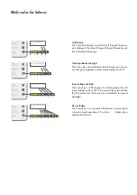
Blink-Codes für Störungen

Netzstörung:

Der Sunny Boy zeigt eine Netzstörung an, wenn die
Netzfrequenz, die Netzspannung oder die Netzfrequenz-
Änderung außerhalb der tolerierbaren Werte liegt.

Netzimpedanz ist zu hoch (ENS):

Der Sunny Boy zeigt diese Meldung, wenn die
Netzimpedanzwerte der ENS außerhalb des tolerierba-
ren Bereichs liegen oder ein Impedanzsprung vorliegt.

Eingangsspannung ist zu hoch:

Der Sunny Boy 1100E zeigt diese Meldung, wenn die PV-
Eingangsspannung über 400 V liegt. Der Sunny Boy
muss dann sofort von der PV-Eingangsspannung getrennt
werden, um  eine Beschädigung zu vermeiden!

Gerätestörung:

Der Sunny Boy hat eine Störung, die den normalen
Betrieb verhindert. Eine Elektrofachkraft muss das 
Gerät überprüfen, wenn diese Störung gehäuft auftritt. 

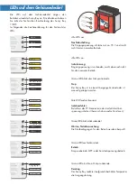
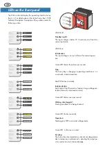
Die gelbe LED leuchtet 3
Mal kurz hintereinander

5 s

3 s

1 s

LED an

LED aus

1 s 1 s

Die Meldung wird 3 Mal
wiederholt und beginnt
dann von vorn.

Die Meldung wird 3 Mal
wiederholt und beginnt
dann von vorn.

5 s

3 s

1 s

LED an

LED aus

Die gelbe LED leuchtet 2
Mal kurz hintereinander

Die gelbe LED leuchtet 4
Mal kurz hintereinander

5 s

3 s

1 s

LED an

LED aus

1 s 1 s 1 s

Die Meldung wird 3 Mal
wiederholt und beginnt
dann von vorn.

Die gelbe LED leuchtet 5
Mal kurz hintereinander

5 s

3 s

1 s

LED an

LED aus

1 s 1 s 1 s

1 s

Die Meldung wird 3 Mal
wiederholt und beginnt
dann von vorn.

Summary of Contents for Sunny Boy 1100E

Page 1: ...y 1100E String Wechselrichter String Inverter Onduleur String Ondulador de Secencias Kurzinstallationsanleitung Quick Installation Guide Instructions d Installation Br ves Instrucciones de Instalaci n...

Page 2: ......

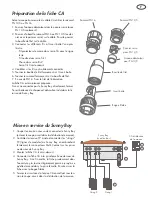
Page 3: ...iebnahme unbedingt 1 Die Inbetriebnahme des Sunny Boy darf nur durch qua lifiziertes Personal erfolgen 2 Beachten Sie beim elektrischen Anschluss unbedingt die unten angegebene Reihenfolge 3 berpr fen...

Page 4: ...Netzanschluss C 2 3 4 5 1 1 Der AC Stecker zum Netzanschluss des Sunny Boy kann handels bliche Netzkabel mit Leitungsquerschnitten von 1 5 mm2 bis 2 5 mm2 aufnehmen 2 Der Stromkreis an dem der Sunny B...

Page 5: ...Boy nicht gleich anschlie en so ver schlie en Sie den Buchseneinsatz mit der ebenfalls im Beipack enthaltenen Verschlusskappe 1 Schalten Sie den Stromkreis ab an dem Sie den Sunny Boy anschlie en woll...

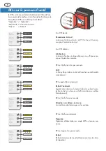
Page 6: ...sschutzes thermisch berwachte Varistoren Gr ne LED erlischt ein Mal pro Sekunde Derating Der Sunny Boy reduziert aufgrund berh hter Temperatur die Ausgangsleistung LED aus LED aus LED aus Alle LEDs au...

Page 7: ...eine Besch digung zu vermeiden Ger test rung Der Sunny Boy hat eine St rung die den normalen Betrieb verhindert Eine Elektrofachkraft muss das Ger t berpr fen wenn diese St rung geh uft auftritt Die...

Page 8: ......

Page 9: ...nny Boy may only be commissioned by qualified personnel 2 Follow the order below when establishing the electrical connection 3 Check the open circuit voltage of the PV strings Voltages above 400 V can...

Page 10: ...absolutely necessary but facilitates reading the LEDs or the Sunny Display Make sure before mounting the Sunny Boy Mounting the Sunny Boy Conditions for electrical connection C 2 3 4 5 1 1 The AC plug...

Page 11: ...he PG16 gland Tighten the bolt of the PG16 gland The AC connector socket is now ready to use Seal the AC connector socket in case you do not insert it in to the Sunny Boy immediately 1 Disconnect the...

Page 12: ...LED flashes constantly Isolation failure Earth fault of the PV panels or failure of surge voltage pro tection thermally monitored varistors Green LED is off once a second Derating The Sunny Boy has de...

Page 13: ...Disconnect the grid and then the PV panels from the Sunny Boy immediately to prevent damage The yellow LED flashes 4 times 5s 3s 1s LED on LED off 1s 1s 1s The yellow LED flashes 5 times 5s 3s 1s LED...

Page 14: ......

Page 15: ...la mise en service 1 Le Sunny Boy ne doit tre mis en service que par du per sonnel qualifi 2 Lors de la connexion lectrique suivre l ordre ci dess sous 3 Examiner la tension vide des lignes de module...

Page 16: ...itions pr alables pour la connexion au r seau C 2 3 4 5 1 1 La fiche CA pour connexion du Sunny Boy au r seau peut recevoir c bles d alimentation usuels avec coupes transversales de 1 5 mm 2 5 mm 2 Le...

Page 17: ...ec le chapeau d obturation inclut dans la liv raison du Sunny Boy 1 Couper le circuit o vous voulez connecter le Sunny Boy enlever le coupe circuit dans la distribution de maison 2 Contr ler la tensio...

Page 18: ...D faut d isolement Le g n rateur solaire a du contact la terre ou bien la pro tection contre les surtensions a failli varistances surveill es thermiquement DEL vert expire fois par seconde D faut D f...

Page 19: ...mesur es sont hors de la plage tol rable Le DEL jaune brille 3 fois 5s 3s 1s DEL allum eDEL teinte 1s 1s La tension d entr e est trop haute Le Sunny Boy montre ce signal si la tension d entr e PV sur...

Page 20: ......

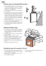
Page 21: ...esto en servicio exclusiva mente por un t cnico cualificado 2 Seguir estrictamente el orden mencionado m s ade lante a la hora de conectar el Sunny Boy 3 Controlar la tensi n en circuito abierto de la...

Page 22: ...s diodos LED o el Sunny Display Criterios para el montaje del Sunny Boy Montaje del Sunny Boy Condiciones para la conexi n a la red C 2 3 4 5 1 1 El enchufe CA para conexi n del Sunny Boy a la red es...

Page 23: ...osca fuertemente pa ra impermeabilizaci n Ahora el enchufe de CA est preparado Si no conecta el Sunny Boy directamente cerrar el orificio de enchufe con el capuch n tambi n incluido en el env o 1 Desc...

Page 24: ...l mente LED verde destella una vez por segundo Esperando comprobando red Se est n comprobando los estados de inicio LED verde es apagado una vez al segundo Fallo Fallo interno o externo descripci n ex...

Page 25: ...e La impedancia de la red est demasiado alta El Sunny Boy ha detectado un fallo bas ndose en los valo res de impedancia de la red no permisibles medidos por la MSD Fallo del dispositivo El Sunny Boy e...

Page 26: ......

Page 27: ......

Page 28: ...SMA Regelsysteme GmbH www SMA de Hannoversche Str 1 5 34266 Niestetal Germany Tel 49 561 9522 0 Fax 49 561 9522 100 www SMA de SB1100E 12 QX1504 TBK SB11E...

Reviews: