


SMA America, LLC
Electrical Connection
Installation Guide
SB50US-80US-eng-IUS112633
41
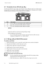
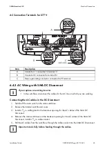
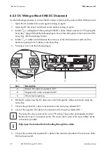
6.4.2 AC Connection without SMA DC Disconnect
1. Switch off the main switch in the main switchbox.
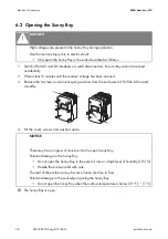
2. Remove the internal switchboard cover.
3. Install a
3
⁄
4
in. cable gland in the enclosure opening for the AC cables of the Sunny Boy.
Observe section 6.2 ”Opening the Sunny Boy” (page 38).
4. Between the main switchbox and the breakout opening for the AC cables, install a
3
⁄
4
in. cable
conduit.
5. Pull the AC cables from the switchbox through the cable conduit into the Sunny Boy.
6. Connect the AC device grounding conductor to the PE terminal labeled
in the Sunny Boy.
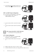
208 V and 240 V System Configuration:
7. Connect conductor L1 (AC conductor 1 or UNGROUNDED) to terminal L1.
8. Connect conductor L2 (AC conductor 2) to terminal L2.
9. Connect conductor N (AC conductor N) to terminal N.
277 V System Configuration:
10. Connect conductor L1 (AC conductor 1 or UNGROUNDED) to terminal L1.
11. Do not use terminal L2.
12. Connect conductor N (AC conductor N) to terminal N.
13. Tighten the AC terminal blocks in the inverter with the following torques:
14. Check that all terminals have the correct wiring and that the cables are secure.
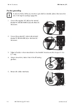
If you replace an existing inverter
• In the switchbox, disconnect the cables for the AC line on which you are working.
Do not connect the Sunny Boy 8000-US to a 208 V grid.
When using grounded 240 V or 208 V Delta grids:
• Connect terminal L2 to the grounded phase.
Open terminal fully before feeding through the cables.
Gray terminal blocks (Weidmüller)
10 … 6 AWG: 18 in-lbs. (2 Nm)
Green terminal blocks (Phoenix)
8 … 6 AWG: 40 in-lbs. (4.5 Nm)
10 AWG: 2 in-lbs. (2.5 Nm)


