5 Settings of Grid Management Services
SMA Solar Technology AG
Technical Information
17
STP60-SHP75-10-Parameter-TI-en-12
5.3
Control Modes
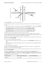
The general approach for the control modes is based on the structure in the technical report of the standard
IEC 61850-90-7 (see the figure below).
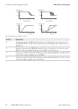
Up to five parameters are used to program the local modes depicted above. The parameter
RmpTmsPT1
is the rise
time from 0% to 95% (equal to 3τ) for the low-pass filter applied on the independent variable (e.g. grid voltage). The
reference table is made of two characteristic curves each containing up to ten break-points. One characteristic curve is
used when the independent variable is increasing and the other when decreasing. In this way, hysteresis can be
included in the reference table. Finally, the parameters
RmpIncTmm
and
RmpDecTmm
are the ramp rates for
increasing and decreasing output values (dependent variable) from the reference table.
Independent ramp rates are only available for control modes for active power, whereas for reactive power the ramp
rates are always given by the parameters
RmpDecTmm_Q
and
RmpIncTmm_Q
. If the input value (independent
variable) of the reference table exceeds the values defining the characteristic curves, the output value (dependent
variable) of the reference table is given as the first or last value in the characteristic curve respectively.
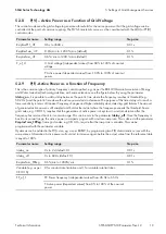
5.3.1
Q(U) - Reactive Power as a Function of Grid Voltage
This control mode uses the grid voltage to generate a reference value for the reactive power so that the grid voltage
can be controlled at the point of common coupling. The control mode contains two additional parameters for
activation. The mode is activated when the active power is above the set threshold and deactivated again when the
active power is below the set threshold. The threshold for activation must be larger than or equal to the threshold for
deactivation. If this control mode shall always be available, set
lock_in_UQ
=
lock_out_UQ
= 0% (only available if
control mode 1 has been selected in the parameter
ModeSelect
).
Parameter name
Setting range
Step size
RmpTmsPT1_UQ
0.6 s to 3600 s
0.01 s
lock_in_UQ
0% to 100% of active power
0.1%
lock_out_UQ
0% to 100% of active power (must be smaller than lock_in_UQ)
0.1%
Q_of_U
U: Grid voltage (independent values) from 80% to 120% of nominal
voltage
-
Q: Reactive power (dependent values) from -100% to 100% of nomi-
nal power
-
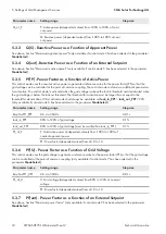
5.3.2
Q(P) - Reactive Power as a Function of Active Power
This control mode uses the active power to generate a reference value for the reactive power so that the grid voltage
can be controlled at the point of common coupling. The independent variable (grid power) can be negative if an
external energy meter is installed and the PV system must compensate for a local load (only available if control mode
2 has been selected in the parameter
ModeSelect
).
Parameter name
Setting range
Step size
RmpTmsPT1_PQ
0.6 s to 3600 s
0.01 s
Summary of Contents for SHP 75-10
Page 21: ......
Page 22: ...www SMA Solar com...

