6 Electrical Connection
SMA Solar Technology AG
22
MC-BOX-12-3-20-BE-en-10
Operating Manual
6.6 Connecting the PV System
Cable dimensioning:
In the event of a short circuit in the PV system cable, short-circuit currents arising in the generator or Grid Connect Box /
NA Box will flow via the unprotected cable between the Multicluster Box and main PV distribution. Size the cables to
match the fusing of the generator or the Grid Connect Box / NA Box.
When planning the short-circuit protection of cables, the PV inverters and Sunny Island inverters may be disregarded, as
their construction precludes any danger to power cables in case of short circuits.
Cable requirements:
Conductor material: copper
Conductor cross-section: 120 mm² to 150 mm²
The power cables must be ground-fault and short-circuit protected.
Procedure:
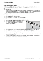
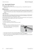
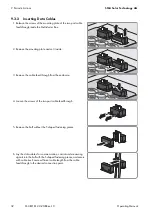
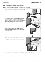
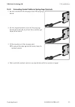
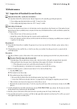
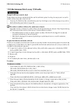
1. Insert the power cables into the Multicluster Box (see Section 9.3.1, page 31).
2. Connect the grounding conductor to the grounding busbar
(AF 17, torque: 15 Nm). To do this, use the screw terminal
included in the scope of delivery.
3. Connect the neutral conductor to the spring-cage terminal
N
at terminal
4. Connect the line conductors to the spring-cage terminals
L1
,
L2
and
L3
at terminal
X104:1-3
.
5. Provide for strain relief of the power cables by attaching them to the appropriate cable support rail. Use the strain
reliefs and counter-troughs provided.
Connection of other energy sources
Instead of a PV system, you can also connect other energy sources (e.g., a small wind turbine system) to the
Multicluster Box.
Cable protection
The Multicluster Box is not a substitute for the distribution board of the PV system (main PV distribution board). Install
a circuit breaker and, if necessary, a residual-current device between the Multicluster Box and the PV system for
protection and disconnection purposes. Make sure all standards and directives applicable at the installation site are
observed.

