Sleipner SEP-IP100 Installation Manual Download Page 7

 7

2705

12

2022

-

SEP IP 100 & SEP IP 130

important

MG_0001

A

B

Pivot
point

1

Ø

2

Lowered rotation power performance

Stronger rotation power performance 

min 1/4

Ø


(Recommended)

min 1/4

Ø


(Recommended)

WD

Water line

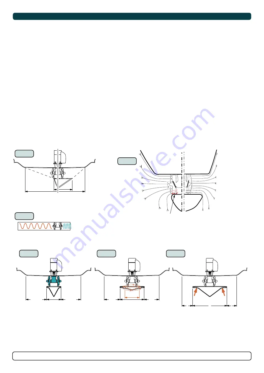
Positioning of the tunnel / thruster

MC_0003

Aim to install the thruster as far forward as possible (1)

Due to the leverage effect around the boats’ pivot point. The distance difference from the boat pivots’ point to the thruster will determine the amount 

of real rotation power for the boat. 


Aim to install the thruster as deep as possible under the waterline (2)

Deeper installations prevent air from being sucked into the tunnel from the surface, resulting in reduced thrust performance and increase noise levels 

during operation. Deeper installations increase water pressure for maximum effi ciency from the thruster.

The centre of the tunnel should be a minimum of 1 x the tunnel diameter below the waterline. The installer must make evaluations based on thruster 

performance, boat type and operating conditions. As a general recommendation, the position of the tunnel should not be a minimum of 1/4 of the 

diameter of the tunnel from the boat keel. 

(NB: This can be overlooked depending on the installation methods defi ned in this manual.) 

1

2

3

4

6

5

MG_0048

Increase tunnel length to protect 

the propeller from water forces 

when high-speed cruising. 

Water 

Forces

Increase tunnel length to 

prevent a circular water vacuum 

cavity between the propeller and 

the hull of the boat.

STANDARD USE

FLAT BOTTOM HULL

HIGH-SPEED OPERATION

Do not allow the variable length of the tunnel walls to vary in length 

excessively. 

EG. the top tunnel wall is x 4 longer than the bottom wall.

Cavitation

Water flow must have 

space to "straighten" 

itself for best 

performance.

The gear leg/ propeller(s) must 

never extend out of the tunnel 

Optimal tunnel length

Achieving the correct tunnel length depends on many factors from the hull type, operation and environmental conditions.

Tunnels should avoid being longer than 4 x the tunnel diameter as this will reduce thruster performance. 

(NB: Installing long length tunnels can flex/ 

bend over time and may require additional support. Consult with a naval architect.)

1.    Do not allow the variable length of the tunnel walls to vary in length excessively. 


EG. The top tunnel wall is x 4 longer than the bottom wall.

2.    If the tunnel is too long, the friction inside will reduce the water speed and thereby the thrust.

3.    If the tunnel is too short (typically only in the bottom section of the tunnel) cavitation problems can occur as water flow will not be able to             

       “straighten” itself before reaching the propeller. This cavitation will reduce performance and increase noise during operation.

Thruster within the tunnel

It is important the propellers and the lower unit/ gear leg must be entirely inside the thruster tunnel. Propellers that protrude from the tunnel will not 

perform as intended.

4.    

Standard Use

       Tunnel length must be long enough to ensure the propellers are not extruding the tunnel. 


5.    

Flat Bottom Hull

       Tunnel lengths must be longer than the standard measurement outlined within the manual to ensure a circular vacuum is not created between the  

       thruster and the bottom of the boat. 


6.    

High-Speed Boats

       Tunnel lengths must be increased to protect the propeller from damage when crashing against the water surface during high-speed cruising. 

(NB:  

       This can include the length of a spoiler)

MC_0003

Tunnel Length

Summary of Contents for SEP-IP100

Page 1: ...MOTOR AS P O Box 519 N 1612 Fredrikstad Norway www sleipnergroup com DOCUMENT ID REVISION DATE LANGUAGE Installation Guide For Pro Ignition Protected DC Thruster Models SEP IP100 SEP IP130 EN I M 2705...

Page 2: ...ct Specifications 5 Proportional Technical Specifications 5 Positioning of the tunnel thruster 6 Tunnel Length 7 Tunnel installation in sail boats 8 Water Deflection 9 Tunnel ends 10 Tunnel installati...

Page 3: ...ge compartments must be separated from the thruster to prevent nearby items becoming dusty dirty NB IP version motors generate dust but are enclosed MC_0425 For thruster systems Do not install the thr...

Page 4: ...Depth 185 7 28 185 7 28 250 9 84 250 9 84 TL Minimum tunnel length 158 6 22 158 6 22 253 9 96 253 9 96 TL recommended Recommended tunnel length 195 7 68 216 8 50 303 11 93 303 11 93 T min Minimum tun...

Page 5: ...212 lbs 80 kg 176 lbs 4 4kw 6hp 20kg 44lbs SE 100 12V 116 kg 256 lbs 100 kg 220 lbs 6 3kw 8 4hp 31kg 68lbs 24V 116 kg 256 lbs 100 kg 220 lbs 6 3kw 8 4hp 31kg 68lbs SE 120 24V 139 kg 306 lbs 120 kg 264...

Page 6: ...r as deep as possible under the waterline 2 Deeper installations prevent air from being sucked into the tunnel from the surface resulting in reduced thrust performance and increase noise levels during...

Page 7: ...ength of the tunnel walls to vary in length excessively EG The top tunnel wall is x 4 longer than the bottom wall 2 If the tunnel is too long the friction inside will reduce the water speed and thereb...

Page 8: ...stead fit the tunnel halfway into the underneath section of the existing hull Strengthen it with a deflector spoiler directing the water flow around the tunnel This will allow installation of the thru...

Page 9: ...tunnel entry The depth and shape of this recess will depend on the boat and the angle facing up down aft of the tunnel insert Normally it is angled slightly down because of the water flow on this are...

Page 10: ...tunnel and thereby reduces the effective tunnel diameter and thrust Turbulence cavitation on the propeller will lessen the thrusters performance and create excess noise 2 For steel aluminium hulls an...

Page 11: ...over the back face 5 Cut the tunnel ends to the desired shape and lightly sand its surface Clean the area with acetone or similar where you are going to apply fibreglass NB Do not cast or add breglass...

Page 12: ...tunnel installed and cast 1 Round the edges with a radius of 10 of the tunnel diameter 2 For steel aluminium hulls make a slope with a length of 10 15 of the tunnel diameter NB If this is not possible...

Page 13: ...manual in your Sleipner product delivery Stern Thruster SLEIPNER AS P O Box 519 N 1612 Fredrikstad Norway www sleipnergroup com DOCUMENT ID REVISION DATE LANGUAGE Installation Guide For DC Electric T...

Page 14: ...leg to ensure it is centred and rotates freely with the same clearance from each blade to the tunnel wall Place top motor bracket to measure the drive shaft has come through the motor bracket at the c...

Page 15: ...end of the shaft spline Tighten with the propeller lock nut 3 Insert the anode to the end of the propeller and tighten the anode holding screw Apply a thread glue Loctite 243 or similar to ensure tha...

Page 16: ...ctly top and bottom NB The motor can be placed in all directions on the motor bracket However ensure the cable terminals are accessible for electrical installation later 6 If you are installing the mo...

Page 17: ...ation Nominal current drawn is listed in the Cross Section Guide for Power Cables chapter The actual voltage at the motor while running the thruster determines the motor RPM and thrust Use larger cabl...

Page 18: ...0 NA NA NA AWG 2 0 2 0 4 0 2 x 2 0 2 x 3 0 2 x 3 0 2 x 4 0 2 x 4 0 2 x 4 0 24V 280 A DIN 300 SAE 570 EN 520 ANL 250 mm 35 35 35 50 50 70 70 95 95 120 120 2 x 95 AWG 2 2 2 1 0 1 0 2 0 2 0 3 0 3 0 4 0 4...

Page 19: ...ed for detailed installation instructions See S Link System Description chapter for detailed information on installation of S Link Power cable and additional S Link components Selection of battery fus...

Page 20: ...ed wire connected to 12VDC or 24VDC To reduce the risk of interference avoid routing the S Link cables close to equipment such as radio transmitters antennas or high voltage cables The backbone must b...

Page 21: ...Control Panel installation please refer to the Installation Guide accompanying the control panel to be installed MC_0398 Control Panel SLEIPNER MOTOR AS P O Box 519 N 1612 Fredrikstad Norway www slei...

Page 22: ...gear house and propeller but NOT anodes sealing rubber fittings or propeller shafts Propeller is fastened correctly to the shaft Propeller turns freely in tunnel The anode and or holding screw is tigh...

Page 23: ...stances of the defect to the best of the Claimant s knowledge including product identification and serial nbr the date and place of purchase and the name and address of the installer Proof of purchase...

Page 24: ...curacies or omissions it may contain Continuous product improvement may change the product specifications without notice Therefore Sleipner Group cannot accept liability for any possible differences b...

Reviews: