background image

Page 150 of 286                                                                                                                                                  Issue 8

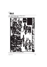
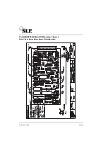
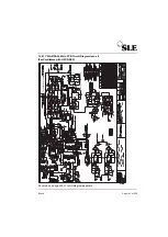
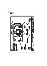
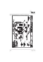
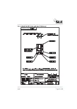
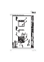
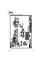
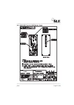
15.10 AS/A0739/02 Motor Drive PCB Issue 1 Sheet 1 (Revision B)

Summary of Contents for 2000 HFO+

Page 1: ...Issue 8 SLE 2000 HFO Ventilator Service manual High Frequency Oscillatory Ventilator ...

Page 2: ...ectronic mechanical photocopy recording or otherwise without prior permission of SLE Copyright SLE 04 01 2013 Manual SM0010 Issue 8 SLE Part Nº N2009 02 SLE Limited Twin Bridges Business Park 232 Selsdon Road South Croydon Surrey CR2 6PL Telephone 44 0 20 8681 1414 Fax 44 0 20 8649 8570 E mail admin sle co uk E mail s should be addressed to the Service Manager Web site www sle co uk ...

Page 3: ...LE2000 HFO Internal Components 22 3 1 Electronic Module 22 3 2 Pneumatic Module 24 3 3 Separating the two modules 25 3 4 Removal of the Oxygen cell 27 3 4 1 Oxygen Cell Mounting 27 3 5 Removal of the motor assembly 29 3 5 1 Motor Assemblies 29 3 5 2 Removal of N2524 60 motor assembly 30 3 5 3 Removal of N2524 61 motor assembly 30 3 5 4 Removal of motor assemblies from pneumatic units fitted with H...

Page 4: ...re check 41 6 1 6 HFO pressure check 41 6 2 6 Servicing 42 7 Overhaul 44 8 Exchanging a Pneumatic Unit 46 9 SLE2000 HFO Set up and Calibration 48 9 1 Recommended equipment 48 10 Setup and calibration 49 11 Operational Verification 66 11 1 Basic Operation 66 11 2 HFO Modulation 68 11 3 Display Timebase 69 11 4 Display Pressure Range 69 11 5 Freeze Push Button 69 11 6 HFO Fail 69 11 7 FAN Fail 69 11...

Page 5: ...or Drive Board Assembly A0739 02 90 14 0 7 Pressure Drift Monitor Board Assembly A0745 01 91 14 0 8 Power Supply Unit 92 14 0 9 Graphic LCD Module 92 14 1 Pneumatic Circuit 93 14 1 1 Pneumatic Layout for a standard HFO 94 14 1 2 Pneumatic Layout for a HFO with HFO NEEP 95 14 1 3 Conventional Ventilation 96 14 1 4 HFO Operation 96 15 Circuit Details 100 15 1 A0700 03 Display Board Assembly 100 15 1...

Page 6: ...e PCB Issue 1 Sheet 2 Revision B 151 15 10 2 CD A0739 03 Motor Drive PCB Circuit Diagram Issue 1 Revision B 152 15 11 AS A0739 02 Motor Drive PCB Issue 2 Revision C 155 15 11 1 CD A0739 03 Motor Drive PCB Circuit Diagram Issue 3 Revision C 156 15 12 AS A0756 HFO Start up Motor PCB Issue 1 159 15 13 AS A0738 02 Alarm PCB Assembly 161 15 13 1 CD A0738 02 Alarm PCB Circuit Diagram 162 15 14 A0745 01 ...

Page 7: ...rtant solenoid failure messages 235 17 1 3 SI 990401 Slightly attenuated alarm sounder for the 12 24V monitor 236 17 1 4 SI 990801 Enhanced EMC 238 17 1 5 SI 000101 Modification of SLE 2000 HFO motor drive circuit board 243 17 1 6 SI 000201 Leak Alarm Trigger Threshold 246 17 1 7 SI 000601 Addition of HFO NEEP 248 17 1 8 SI 020901 Cleaning Disinfection and Sterilisation of SLE ventilators 269 17 1...

Page 8: ...Page 8 of 286 Issue 8 This page is intentionally blank ...

Page 9: ...Issue 8 Page 9 of 286 Introduction ...

Page 10: ...eed motor This flow of driving gas is adjusted by the oscillatory pressure regulator mounted in the pneumatic module ensuring a constant oscillatory pressure waveform at all operating frequencies This rotating driving pressure produces oscillatory action in the patient circuit with an active expiratory flow of gas The oscillatory flow of gas is supplied from a separate rotating jet therefore it is...

Page 11: ...Issue 8 Page 11 of 286 Ventilator Control Description ...

Page 12: ...Ventilator Control Description The SLE 2000 HFO consists of two linked modules Electronic and Pneumatic 2 1 Front Panel Electronic Module Pneumatic Module 1 2 3 4 5 6 7 8 9 10 11 12 13 14 15 16 17 18 20 21 22 23 24 25 26 27 19 ...

Page 13: ...eset button 11 Alarm mute button 12 Manual breath button 13 Flow Pressure trigger switch 14 Pressure wave selector switch 15 Airway pressure monitoring selection switch 16 PTV sensitivity control 17 O2 blender control 18 O2 inlet 19 Medical air inlet 20 Inspiratory pressure regulator 21 Oscillator pressure regulator 22 CPAP PEEP pressure regulator 23 Fresh gas to patient port 24 Exhalation block 2...

Page 14: ... panel 2 2 1 Back panel features 1 Auxiliary Output 2 FIO2 Calibration adjustment 3 Running time meter pneumatic module 4 Fuse holders 5 Product information plate 6 FIO2 Adjustment Tool 7 Fan and Filter 8 Filter only 1 2 3 4 5 6 7 8 ...

Page 15: ...Issue 8 Page 15 of 286 2 3 Side panel 1 Fixed jet 2 Rotating jet Note Exhalation block removed 2 1 ...

Page 16: ...ewed from the left Position of the boards within the electronic module 1 HFO Main Board Assembly A0736 04 2 Ventilator CPU Board Assembly A0702 05 3 Motor Drive Board Assembly A0739 02 Note Boards 1 2 and 3 are polarised by the position of the edge connectors thus preventing the boards being inserted into the wrong sockets 3 2 1 ...

Page 17: ...ns within the electronic unit viewed from the right 4 Alarm Board Assembly A0738 02 5 Pressure Drift Monitor Assembly A0745 6 Front Panel Board Assembly A0700 03 and LED Display Board Assembly A0701 02 Note both these boards are mounted on the rear face of the front panel 5 4 6 ...

Page 18: ...lock 3 SV5 Solenoid valve Beneath bracket 4 SV4 Solenoid valve HFO solenoid valve 5 SV3 Solenoid valve 6 SV2 Solenoid valve 7 SV1 Solenoid valve 8 Volume chamber 9 Blender 10 Regulator Reg 3 Regulator 3 test point indicated by arrow 11 PAPST L fan 12 25 way plug 13 O2 cell manifold 1 2 8 9 11 10 13 5 6 7 4 12 3 ...

Page 19: ...olenoid valve Beneath bracket 4 SV4 Solenoid valve HFO solenoid valve 5 SV3 Solenoid valve 6 SV2 Solenoid valve 7 SV1 Solenoid valve 8 Shuttle Valve 9 Volume chamber 10 Blender 11 Regulator Reg 3 Regulator 3 test point indi cated by arrow 12 PAPST L fan 13 25 way plug 14 O2 cell manifold 1 2 9 10 12 11 14 5 6 7 4 13 3 8 ...

Page 20: ...Page 20 of 286 Issue 8 This page is intentionally blank ...

Page 21: ...Issue 8 Page 21 of 286 Access to Internal Components ...

Page 22: ...c Module 1 Remove the two screws A from the retaining bar 2 Remove the four screws B Two from either side of the cover 3 The cover can now be removed Slide the cover forward Step 1 Then lift the cover away from the ventilator Step 2 4 Loosen but do not remove the two bracket support screws A and the single EM shroud fixing screw B Access to the screws is from the direction of the arrows under the ...

Page 23: ...rouds from the ventilator taking care not to damage the metal contact fingers on the edges of the shrouds 7 To remove the PCB assemblies remove the retaining thumbscrews A 8 This releases the PCB s The boards can now be removed by sliding them out of the support racking Assembly is the reversal of removal A A A ...

Page 24: ...tilator 3 Remove two screws indicated from the base of unit Warning take care not to undo the ventilator pole fixing screws A as this may cause the ventilator to fall from the stand 4 Lift the complete unit from stand 5 The unit can then be placed on the work surface upside down Assembly is the reversal of removal A A A A ...

Page 25: ...e 25 of 286 3 3 Separating the two modules Invert the ventilator to gain access to the base of the pneumatic unit 1 Remove the four screws 1 2 Remove proximal airway pressure tube connection 1 1 View A 1 View A 1 ...

Page 26: ...e 8 3 Remove fresh gas monitoring tube connection 4 Loosen both locking screws and disconnect 25 way plug It is now possible to separate the pneumatic module from the electronic chassis Assembly is the reversal of removal ...

Page 27: ...or has two methods of mounting the Oxygen cell The first method the oxygen cell is trapped between the manifold and a foam pad Photograph A The second the oxygen cell is screwed directly into the manifold Photograph B 3 4 1 1 Method A for Trapped cell 1 Disconnect the cell connector A 2 Remove the two screws B retaining the manifold and lift it clear Photograph A Photograph B A B B ...

Page 28: ...en the cell and the mounting base and that the gas seal O ring is fitted to the manifold After refitting recalibrate the cell 3 4 1 2 Method B for Screw in cell 1 Disconnect the cell connector D 2 Remove the two screws E retaining the manifold and lift it clear 3 Unscrew the old cell 4 Assembly is the reversal of removal 5 Screw in the new cell Part No N2191 and reconnect the electrical connector ...

Page 29: ...nd N2524 61 The first step is to ascertain which motor assembly is fitted to your ventilator The method of identifying which motor assembly is fitted is a follows The N2524 60 motor assembly is connected to the ventilator via a 9 pin D connector See photograph A The N2524 61 motor assembly is connected to the ventilator via a 8 way Molex connector See photograph B Photograph A Photograph B N2524 6...

Page 30: ...e grommet and cable from retaning slot 2 The disassembly is now the same for both motor assemblies fitted to a pneumatic unit without HFO NEEP for a ventilator with HFO NEEP follow the procedure on page 32 3 Remove the fresh gas relief valve hose 3 by cutting cable tie 4 and easing the hose off the connector 4 Remove the NEEP hose 5 by unscrewing the retaining nut 6 from the pneumatic connector 1 ...

Page 31: ... fresh gas relief valve cover 10 8 Remove the fresh gas relief valve cover 10 9 Remove the two screws 11 securing the orifice block 10 Remove the three screws 12 retaining the motor assembly 11 Remove the sub assembly by tilting the top towards you Replace sub assembly in reverse order The motor assembly is avaliable as a service exchange part 3 2 7 SV4 9 8 10 11 11 12 12 12 ...

Page 32: ...1 retaining the Shuttle valve 2 Remove the HFO jet hose 2 from the SV4 solenoid valve tee connection 3 3 Remove the fresh gas relief valve hose 4 by cutting cable tie 5 and easing the hose off the connector 4 Remove the NEEP hose 6 by unscrewing the retaining nut 7 from the pneumatic connector at the motor assembly partition 1 1 2 3 5 4 6 7 ...

Page 33: ... 9 6 Remove the fresh gas relief valve cover 9 7 Remove the two screws 10 securing the orifice block 8 Remove the three screws 11 retaining the motor assembly 9 Remove the sub assembly by tilting the top towards you The motor assembly is avaliable as a service exchange part 8 9 10 10 11 11 11 ...

Page 34: ...Page 34 of 286 Issue 8 This page is intentionally blank ...

Page 35: ...Issue 8 Page 35 of 286 Maintenance ...

Page 36: ... returned in its original box Remove the protective film from the LCD screen Clean disinfect and sterilize in accordance with the instructions in section 4 2 Remove the inlet air and O2 gas port caps Retain for future use 4 2 Cleaning and disinfection of an in service ventilator The table 1 outlines the areas of the ventilator which can be uniquely cleaned disinfected and sterilized Before cleanin...

Page 37: ...ilencer 4 3 Cleaning method Note Cleaning is an essential prerequisite to disinfection and sterilization Ventilator For cleaning use three clean disposable absorbent non shedding cloths Wipe clean with the first cloth using a hand hot water mild general purpose detergent solution as prescribed by the appropriate hospital authority Do not overload the cloth with liquid Remove the water mild general...

Page 38: ...on 4 5 Sterilization method The silencer SLE part Nº N2186 and exhalation block SLE part Nº N0635 60 must be sterilized between use on patients The ventilator cannot be sterilized The exhalation block must be cleaned as an essential prerequisite to sterilization Autoclave with pure dry saturated steam at 134ºC 277ºF Allowable variation of temperature of 3ºC at 220kPa 32psi with a minimum holding t...

Page 39: ... dry saturated steam at 134ºC 277ºF Allowable variation of temperature of 3ºC at 220kPa 32psi with a minimum holding time of 3 minutes or 121ºC 248ºF Allowable variation of temperature of 3ºC at 96kPa 14 1psi with a minimum holding time of 15 minutes The filter can be autocalved a maximum of 25 times within its anticipated service life of 12 months For other makes of bacterial filter please refer ...

Page 40: ...est With the FIO2 blender set to 60 remove in turn both air and oxygen supplies Check that in each case the alarm sounds and on replacement the alarm cancels 6 1 3 Condition of O2 Cell Set blender to 21 and remove O2 supply Observe that displayed FIO2 is 21 Reconnect O2 supply and remove air supply Set blender to 100 and observe that displayed FIO2 is 100 For adjustment See Oxygen Calibration A073...

Page 41: ...d be between 37 and 43 cmH2O 6 1 5 CPAP pressure check Set ventilator to CPAP HFO mode off Check that the CPAP pressure regulator can be set up to produce a pressure of 30 cmH2O 6 1 6 HFO pressure check Check that the Oscillator pressure regulator can be set up to produce delta pressure of 150cmH2O with the ET tube in the patient circuit occluded and the HFO rate set to 3Hz ...

Page 42: ...spection and cleaning of all exterior surfaces controls attachments and accessories Removing of the covers and cleaning all dust from the interior of the unit Replacement of all 3 cooling fan filters Two mounted on the back panel and one on the side Access to the filters is gained by un clipping the fan covers Visual inspection of all tubing electrical wiring connectors crimps screws nuts hardware...

Page 43: ...Issue 8 Page 43 of 286 Overhual ...

Page 44: ...placement of INSPIRATORY CPAP and OSCILLATOR regulators Replacement of motor assembly Service exchange unit N2524 60 or 61 Check operation and general condition and replacing where necessary the following components Solenoid valves SV2 SV3 and SV5 Tubing and connectors Battery holder Alarm sounders Mode wave shape frequency range switches Pressure relief valve Re calibration and testing which will...

Page 45: ...Issue 8 Page 45 of 286 Exchanging a Pneumatic Unit ...

Page 46: ...n the A0702 05 board Step 9 Buffered transducer output on the A0702 05 board Step 10 Maximum Inspiration Time Check A0702 05 board Step 11 Re insert the A0736 04 PCB Step 12 Motor Drive Board A0739 02 Step 13 Scaling of pressure LCD display on the A0736 04 board Step 15 HFO rate check Step 17 Motor Stall Alarm A0736 04 board Step 18 Fan Fail Alarm Verification A0736 04 board Step 19 Internal Press...

Page 47: ...Issue 8 Page 47 of 286 Setup and Calibration ...

Page 48: ...syringe 9 A calibrated oxygen analyser able to resolve 0 5 O2 10 Flow regulator assembly This item is made up from 3 pieces of flexible tubing a Y piece connector a 0 2 bar relieving regulator and applicable hoseadaptors See section Step 25 on page 59 for details of configuration 11 A dummy load resistor of 15 Ohms 1 5W 12 3 pieces of flexible tubing a Y piece connector to connect ventilator syrin...

Page 49: ... display board ribbon cable from connector PL1 Remove the PCB retaining screw from the board and slide the board out Caution Protect the board against static damage Step 3 Adjustment of power supply voltage Caution Use a insulated screwdriver to adjust R26 R26 is located on the left hand side half way down within the power supply housing When viewed from the front Remove the A0736 04 board and ins...

Page 50: ...8 adjusting RV10 to ascertain the two points where the voltage rises from 0V to 5 12V then set RV10 to midway between these positions and to check the setting measure the voltage on U3 pin 11 is a continuous 5 12V Note This is factory set and should not require adjustment a With PTR1 ports open to atmosphere monitor voltage at U13 pin 5 Adjust offset preset potentiometer on transducer assembly RZ ...

Page 51: ...voltage at DIFF vary the pressure to the proximal airway port over the complete range approx 140 to 70cmH2O on the pressure display Adjust RV3 until the voltage measured at DIFF is the same at 140cmH2O as it is at 70cmH2O to within 20mV DIFF should be in the region of 8V Note This is factory set and should not require adjustment a With PTR1 ports open to atmosphere monitor voltage at right hand pi...

Page 52: ...ch to MIN Monitor U18 pin 26 check that the voltage is 1 91V If the voltage at U18 pin 26 is out of specification adjust as described below With PTR1 ports open to atmosphere adjust RV2 to give 1 91V Connect the PTR1 port Port B to the RT200 and the 2ml syringe via the flexible tubing and Y piece connector and set up a pressure of 140cmH2O Adjust RV5 so that U18 pin 26 is 4 73V Check the ventilato...

Page 53: ...ive 6 60V 0 05mv For a final check set up a pressure of 70cmH2O Check that the buffered transducer output PLB pin 23b is 0 21V Reconnect the internal tube to PTR1 Port B Step 10 Maximum Inspiration Time Check A0702 05 board With the ventilator still in CPAP mode With the Insp Time control turned fully clockwise check that the display shows 3 00 secs If the display does not show 3 00 secs adjust RV...

Page 54: ... pressure LCD display on the A0736 04 board Remain in CPAP mode Connect a pressure source 2ml syringe to PTR1 on the A0702 05 board Monitor TP2 Set up a pressure of 140cmH2O 0 5cmH2O Adjust P14 to give 4 79V 0 01V Remove pressure source from PTR1 port Set low alarm to 0 cmH2O Confirm that the displayed low alarm level coincides with the displayed pressure level Reconnect internal tube to PTR1 and ...

Page 55: ... CPAP with HFO mode set to EXP Adjust HFO peak to peak delta p pressure to 20cmH2O approx Monitor the buffered transducer output Pin 1 on the auxiliary output using a calibrated oscilloscope Verify that minimum HFO rate is 3Hz 333ms 3ms and that maximum HFO rate is 20Hz 50ms 0 5ms Turn the HFO mode to OFF Step 16 One second timer A0736 04 board Set the ventilator mode to CMV Monitor TP6 using a di...

Page 56: ...heck that the HFO fail alarm is activated and that HFO driving gas is shut off Drop the high alarm below the waveform by approximately 5cmH2O to check that the gas supply to the patient is cut off Turn the HFO mode to OFF Step 18 Fan Fail Alarm Verification A0736 04 board Short out JP3 emulating Fan2 fail and JP4 emulating Fan1 fail in turn and verify that the fan fail alarm is activated in each i...

Page 57: ...ct the air supply Remove the connecting hose and refit the plug to the test point Re connect the air supply Step 20 O2 Cell Flow Needle Valve Remove the dump plug on the O2 cell manifold and connect the manifold to the RT200 Remove the Fresh Gas and Dump manifold cover Monitor flow and adjust the needle valve marked Dump to 3LPM 0 25LPM Remove the connecting hose from the O2 cell manifold and repl...

Page 58: ...Replace the Fresh Gas and Dump manifold cover Remove card wedge to release the pressure relief ball bearings Turn the ventilator mode to OFF Step 23 HFO High Pressure Dump Fit a standard patient circuit with a test lung at the ET connector Set the blender to 60 Set the ventilator mode to CMV Confirm that the fresh gas solenoid SV2 is de activated at a position of 5cmH20 above the HIGH alarm settin...

Page 59: ...he Air and O2 supply from the ventilator Remove the A0736 04 board and insert the dummy load resistor 15 Ohms 1 5W between PLA 1a b and PLA pin 32a b Turn the ventilator mode to CPAP Connect DVM between pin 1 and pin 3 of PTR2 With PTR2 ports open to atmosphere adjust RV500 to give 0 00V 1mV Re connect the tubing to the PTR2 ports Re connect the Air and O2 supply to the ventilator Then wait approx...

Page 60: ... board and re connect the ribbon cable PL1 Step 26 Post de energisation delay on the A0702 05 board Set up the ventilator electrically and pneumatically Fit a standard patient circuit with a 2ml syringe fitted to the ET manifold Note This is factory set and should not require adjustment With a dual beam oscilloscope connect channel 1 to U200 2 inverted and channel 2 to U200 4 Timebase 100ms cm sen...

Page 61: ...Set respiratory pressures of 30 0cmH2O Set High and CPAP alarms to 35 and 5 cmH2O respectively Turn PTV sensitivity control fully clockwise Switch ventilator into PTV mode and slowly draw 2ml of air from the tracheal port at an approximate rate of 2ml per 1 2 second repeatedly Starting with RV202 in the fully clockwise position adjust gradually anticlockwise until ventilator triggers reliably at t...

Page 62: ...and 5 cmH2O respectively Turn PTV sensitivity control fully clockwise Switch ventilator into PTV mode and slowly draw 2ml of air from the tracheal port at an approximate rate of 2ml per 1 2 second repeatedly c Starting with P2 on A0746 PCB fully counterclockwise adjust gradually clockwise until ventilator triggers reliably at this degree of inspiratory effort d Re adjust P1 on A0746 PCB to give 2 ...

Page 63: ... Maximum Inspiratory Pressure Set high pressure alarm fully clockwise Turn PIP regulator to its maximum clockwise position and the CPAP regulator fully anticlockwise With air and O2 pressures at 4 Bar and the inspiration time control set to 3 0 seconds press the manual breath push button and ensure that the PIP pressure attains 60cmH2O Then reduce air and O2 input pressures to 3 5 Bar ensuring PIP...

Page 64: ... Step 33 Fresh Gas Relief Valve setup Note This is factory set and should not require adjustment Remove the patient circuit and re attach the flow regulator assembly to the ventilator fresh gas port and the RT200 or equivalent as per the diagram Occlude the relieving regulator and note the pressure at which the relief valve dumps fresh gas Remove the fresh gas relief valve Using the special tool S...

Page 65: ...h the blender set to 60 O2 decrease the air supply pressure to the ventilator and note that the blender alarm is activated when the air pressure is approximately 30psi less than O2 pressure Gradually increase air pressure until the alarm is de activated Note that O2 concentration is between 57 and 63 Restore air pressure to 4 Bar Step 35 Oxygen Calibration A0738 02 Board a With blender set to 100 ...

Page 66: ...0 1 sec to 3 0 sec shall be obtained and that this adjustment can be monitored on the INSP TIME display 7 Switch HFO successively to EXP INSP and CONT modes Ensure that manual breaths are not delivered in any HFO modes but OFF 8 Set pressure display switch to MIN position By selecting a range of inspiratory pressures from 0 cmH2O to 60 cmH2 O in 10 cmH2O steps ensure accuracy of digitally displaye...

Page 67: ...ely 1 second intervals to cycle ventilator and observe that the digitally displayed MEAN pressure gradually rises to 10 cmH2O in a period of 30 seconds 16 Select CMV mode HFO off Set a CPAP pressure of 0 cmH2O and an INSP pressure of 20 cmH2O Set an INSP time of 0 5 seconds and a CMV rate of 60 BPM Set CYCLE FAIL alarm level to 10 cmH2O HIGH alarm level to 30 cmH2O and CPAP alarm level to 5 cmH2O ...

Page 68: ...piratory phase of pressure cycle only 3 Switch HFO mode to INSP Observe that HFO modulation occurs during inspiratory phase of pressure cycle only 4 Switch HFO mode to CONT Observe that HFO modulation occurs during both inspiratory and expiratory phases of pressure cycle 5 Switch HFO mode to OFF Check that HFO modulation does not occur during any phase of pressure cycle 6 Select PTV mode With HFO ...

Page 69: ...After 1 minute the display should revert to updating mode 2 By pressing FREEZE push button repeatedly check that the FREEZE function can be toggled on and off 11 6 HFO Fail Select CPAP mode Switch HFO to CONT mode Set up an HFO delta pressure of 20 cmH2O at 3Hz Short out A0736 02 JP1 Check that HFO pressure modulation is suppressed in less than 1 second and that the HFO FAIL audible and visual ala...

Page 70: ...p breath is initialised 3 Check operation of the PTV trigger system in both FLOW and PRESSURE switch settings FLOW trigger will only work with an SLE 2100 VPM connected to the AUX O P socket 11 10 SIMV Mode Check operation of the SIMV trigger system ensuring that the back up LED is activated during backup breaths Check that the SIMV BPM rate may be controlled by adjustment of the BPM control and d...

Page 71: ...ce up to 60 cmH2O inspiratory airway pressure in its fully clockwise position Check that INSPIRATORY pressures are in accord with decal markings 3 With the INSP regulator turned fully anti clockwise Check that the OSCILLATOR pressure regulator can be set to produce up to 150 cmH2O Peak to peak pressure with the ET tube occluded and HFO rate set to 3Hz 4 With the above settings check that the mean ...

Page 72: ... the pressure to 6cmH2O and hold ensuring that the warning message is displayed again 4 Finally adjust the pressure to 3cmH2O and hold Check that the warning message is cleared 5 Disconnect the 2ml syringe and tubing 11 15 HFO NEEP Verification This verification is only for ventilators fitted with HFO NEEP 1 Set vent to HFO Cont and set the frequency to 10Hz Set the CPAP regulator fully anti clock...

Page 73: ...tilator Set the ventilator mode to CPAP CPAP 0cmH20 PIP 60 cmH20 Low alarm 0cmH20 High alarm 60cmH20 Set the ventilator mode to CMV Set the ventilator as follows BPM 60 INSP time 0 5s The the waveform should just be tripping both high and low alarms The SLE2100 VPM should display Max Mean and Min pressures within 1cmH20 of the ventilator If the readings differ by a value greater than 1cmH20 repeat...

Page 74: ...Page 74 of 286 Issue 8 This page is intentionally blank ...

Page 75: ...Issue 8 Page 75 of 286 Troubleshooting Chart ...

Page 76: ...arameter Adjust 15 LPM Fresh Gas needle valve Adjust RV501 to trip alarm at 30 cmH2O Replace solenoid Block Alarm audible visual Fresh gas filter blocked Fresh gas restrictor blocked Replace Autoclaveable filter P No N2029 Replace circuit P No N2198 Blender Alarm audible when both gases connected Alarm shuttle sticking Air O2 differential pressure exceeded Compressor failure Remove both gases and ...

Page 77: ...ace belt and set up assembly as per service manual Set up as per service manual See Tachometer opto interrupter Wheel Alignment on page 59 Fan Alarm audible visual Faulty fan assembly Replace assembly with SLE approved part System Fail audible visual Ensure 5V is present at PSU Replace PSU CPAP Unable to set desired pressure Faulty patient circuit Incorrectly assembled patient circuit Exhalation b...

Page 78: ...Reset alarm setting OSCILLATION PRESSURE Unable to set desired pressure Faulty patient circuit Incorrectly assembled patient circuit Exhalation block located incorrectly Regulator cap is in LOCKED position Jammed regulator Jet nozzle blocked High alarm condition Replace circuit Reassemble as per drawing supplied with circuit Relocate the block assembly Pull regulator cap out to release from locked...

Page 79: ...dummy load LCD measurements vary from that displayed by pressure display Calibration of transducer Verify and adjust as required the calibration of PTR1 to ADC Buffered output Wave form has a slow rise time Water in proximal airway line PTR1 subjected to water ingress Replace patient circuit Trace tubing and remove water Replace PTR1 calibrate ...

Page 80: ...Page 80 of 286 Issue 8 This page is intentionally blank ...

Page 81: ...Issue 8 Page 81 of 286 Technical Specification ...

Page 82: ...FO Ventilation Modes OFF EXP INSP CONT Frequency Range 3 20Hz 1Hz resolution Maximum achievable delta and mean pressures are dependent on the characteristics of the patient circuit and patient lung The following figures are given for an N2387 60 patient circuit and a lung with an airway resistance of 100cmH2O l sec and a compliance of 1ml cmH2O Delta Pressure Range 0 150cmH2O For ventilators witho...

Page 83: ...H2O Oscillator not scaled min max 13 4 Controls Conventional ventilation mode switch OFF ALARM TEST CPAP CMV PTV SIMV BPM Control ten turn 1 to 150BPM INSP TIME Control ten turn 0 10 to 3 00 seconds min exp time 0 25 seconds Pressure Display Switch MAX MEAN MIN Pressure Wave Switch Slow or Fast rise Manual Breath Push button Invokes a single manual breath Alarm Mute and Reset Push buttons Mute act...

Page 84: ...P Pressure Control 0 to 30cmH2O typ Inspiratory Pressure Control 0 60 cmH2O min Air Oxygen Blender Control 21 100 13 5 Alarms Audible only Loss of mains supply Battery powered alarm Loss of Air or O2 supply Blender alarm Audible and Visual HIGH CIRCUIT PRESSURE CYCLE FAIL LOW CIRCUIT PRESSURE LOW DELTA P PRESSURE IN HFO ONLY MODE HIGH DELTA P PRESSURE IN HFO ONLY MODE OXYGEN CONCENTRATION CHANGE F...

Page 85: ... 120V 50 60Hz Fuse T2 0A Air and O2 3 5 bar Operating Environment Temp 10 40 C Humidity 0 90 Size Ventilator only 38cm W 39cm H 33cm D Height on pole 141cms Weight Ventilator Only 16 Kgs Constructed to conform to EN60601 1 IEC 601 2 12 and EN60601 1 2 Patient Circuit Required Model N2198 Single use Model N2387 60 Re usable ...

Page 86: ...tions Software is provided by the ROM U6 Analogue input parameters from panel control settings BPM rate inspiration time and high pressure are converted to digital 8 bit words by the ADC U18 which scans each input in turn Open circuit input fault conditions are detected by software and pull up resistor array RU3 Switched input parameters Mode Reset Mute and Pressure display Mode are scanned by U12...

Page 87: ...as failure pressure transducer PTR2 monitors the fresh gas supply pressure and acti vates the audible alarm BZ2 and also drives the leak alarm LED should the pressure fall below 30 cmH2O If the pressure rises above 160 cmH2O then the block LED is operated and the audible alarm will activate The A0746 board is mounted on the A0702 Board This accepts a flow signal from the external SLE2100 VPM monit...

Page 88: ...cuit then the output of U24 goes to logic 1 and enables the fan fail alarm via D2 or D3 MOS1 and MOS4 hold the reset pins of U24 inactive as long as there are motor pulses U24 is reset during power up or if motor pulses fail and enables the fan fail alarm 14 0 4 4 Processor System All alarm parameters are determined by potentiometer voltages representing fail to cycle low and high pressure thresho...

Page 89: ...associ ated components which condition the cell output voltage to the range 0 4 5V This voltage is then presented to the ADC U18 4 on the A0702 05 PCB and is used to display the FIO2 The alarm board also contains a battery powered alarm circuit consisting of BT1 and BZ3 The circuit is completed when normally closed relay RL1 on the A0702 05 PCB is de energised as would happen in the event of a pow...

Page 90: ...which in conjunction with the L298N U2 provides 4 outputs to drive the HFO stepper motor This cir cuit is operative in all HFO modes 14 0 6 2 HFO Start up Motor PCB assembly A0756 This PCB may be fitted to Revision B Motor drive board A0739 02 issue 1 The PCB is positioned on connector U3 of the main board and carries RC4152 that would originally be positioned on the board The purpose of the board...

Page 91: ...econdly to provide an 8V positive bias to the differential voltage output from U1A Arithmetically the output from U1A is the sum of the PTR1 signal and 8V minus the signal from PTR1 on the A0702 board This differential voltage with 8V offset is applied to the window comparator comprising U1C and U1D The window comparator will provide an output if the differential voltage Diff passes above the volt...

Page 92: ...OM and RAM The LCD is a transmissive type with CCFL Cold Cathode Fluorescent backlighting provided by a tube mounted on the lower edge of the module The cold cathode tube is powered by an inverter mounted on the A0739 02 board The inverter provides an ac voltage of 900V rms The digital interface to the LCD module consists of a 20 way ribbon cable comprising both data and control lines Also the neg...

Page 93: ...Issue 8 Page 93 of 286 14 1 Pneumatic Circuit For access to the pneumatic unit See Pneumatic Module on page 24 Below is a schematic representation of the SLE 2000 HFO pneumatics ...

Page 94: ...Page 94 of 286 Issue 8 14 1 1 Pneumatic Layout for a standard HFO The positioning of the pneumatic components is shown in the following schematic ...

Page 95: ...Issue 8 Page 95 of 286 14 1 2 Pneumatic Layout for a HFO with HFO NEEP The positioning of the pneumatic components is shown in the following schematic ...

Page 96: ...nternal regulator which regulates the blended gas to a working pressure of 30 psi NV2 sets a 2 LPM bleed to atmosphere See Pneumatic Circuit on page 93 This bleed is fed to the oxygen monitoring cell whose output is connected to the digital FIO2 display circuitry in the electronics module RV2 is a pressure relief valve operating at 200 cmH2O that is activated if the Fresh Gas port is occluded NV1 ...

Page 97: ... also serves to modulate the HFO driving gas pressure in various ways during conventional ventilation that is during the inspiratory phase or during the expiratory phase thus allowing combined modes of HFO and conventional ventilation An additional safety solenoid SV5 is incorporated in the HFO pressure line along with SV4 This solenoid is only energised open when an HFO mode is selected In all ot...

Page 98: ...Page 98 of 286 Issue 8 This page is intentionally blank ...

Page 99: ...Issue 8 Page 99 of 286 Circuit Details ...

Page 100: ...Page 100 of 286 Issue 8 15 Circuit Details 15 1 A0700 03 Display Board Assembly ...

Page 101: ...Issue 8 Page 101 of 286 15 1 1 CD A0700 03 Display Board Circuit Diagram ...

Page 102: ... 4 00 Each ITEM 5 D0406 1N4148 2 00 Each D1 D2 D0546 LED Red Rectangular LSB480EH 1 00 Each LED 7 D0590 Display 7 Segment MAN4640A 16 00 Each DISP 1 7 DISP 9 17 M0718 Label PCB Identification 1 00 Each ITEM 7 R0416 150R Resistor 1 0 25W SMA0207 1 00 Each R407 R0424 330R Resistor 1 0 25W SMA0207 1 00 Each R408 S0212 IC Socket 16 way DIL 2 00 Each SK1 SK2 S0242 IC Socket 14 way DIL 1 00 Each ITEM 3 ...

Page 103: ...Issue 8 Page 103 of 286 15 2 A0701 02 LED PCB Assembly ...

Page 104: ...Page 104 of 286 Issue 8 15 2 1 CD A0701 02 LED Board Circuit Diagram ...

Page 105: ... Component Reference s J0701 LED pcb blank 1 00 ITEM 1 PCB D0308 LED Green Rectangular LGB480EH 3 00 LED2 3 4 D0508 74HC00 1 00 U400 M0307 Terminal Pin Pcb single sided 13 00 ITEM 5 Wire pin 1 10 X O N R0463 10K Resistor 1 0 25W SMA0207 2 00 R403 404 R0416 151R Resistor 1 0 25W SMA0207 3 00 R401 R402 R405 S0242 IC Socket 14 way DIL 1 00 ITEM 6 U400 M0718 Label PCB Identification 1 00 ITEM 7 ...

Page 106: ... AS A0702 05 issue 3 on page 114 and circuit diagram CD A0702 05 issue 3 on page 116 Also see service information SI 000201 Leak Alarm Trigger Threshold on page 246 Alarm sounder failing to operate in fresh gas blocked conditions AS A0702 05 Issue 3 As above CD A0702 05 Issue 4 Modification of circuit diagram to show track cut between C500 to U500 pin 7 Connection of link between C500 and U500 pin...

Page 107: ...Issue 8 Page 107 of 286 15 3 AS A0702 05 CPU PCB Issue 2 Sheet 1 of 2 ...

Page 108: ...Page 108 of 286 Issue 8 15 3 1 AS A0702 05 Issue 2 Sheet 2 of 2 ...

Page 109: ...Issue 8 Page 109 of 286 15 3 2 CD A0702 05 CPU PCB Circuit Diagram Issue 2 A3 version on page 211 of circuit diagram appendix ...

Page 110: ...Each C9 201 202 C0461 33pF Capacitor 100V 10 Ceram 2 00 Each C13 C14 C0462 luF Capacitor 50 63V 10 MKS2 14 00 Each C5 7 11 17 24 C29 C200 C205 D0284 BZX79C4V7 was BZY88C 4v7 1 00 Each D3 D0288 LM358N 1 00 Each U500 Pt No D0586 when pre fix D0298 ICM7218D1J1 28 Pin Harris 2 00 Each U1 U2 D0305 ADC0809CCN NSC 1 00 Each U18 D0320 74HC132N 1 00 Each U3 D0336 BC337 4 00 Each Q1 Q2 Q500 Q502 D0402 lN400...

Page 111: ...18 1 00 Each R34 R0226 ll0K Resistor 1 0 25W 1 00 Each R208 R0228 8K2 1 50PPM 0 25W 1 00 Each R32 R0268 SK1 Resistor 1 0 25W SMA0207 1 00 Each R36 R0337 3K3 Resistor 1 0 25W SMA0207 1 00 Each R23 R0349 24K Resistor 0 25W 1 1 00 Each R39 R0350 1K x 8 Resistor Network 1 00 Each RU2 R0351 l0K x 8 Resistor Network 1 00 Each RUl R0416 150R Resistor 1 0 25W SMA0207 7 00 Each R25 R29 R509 R511 R0428 470R...

Page 112: ...ITEM 8 U7 8 11 U500 S0242 IC Socket 14 way DIL 9 00 Each ITEM 9 U3 4 9 13 15 17 200 20 T0205 Alarm Transducer Bracket 1 00 Each ITEM 3 T0683 Handle pcb 1 00 Each ITEM 2 V0403 2 0K Trimmer 1 00 Each RV4 V0404 5 0K Trimmer cermet top adjust 1 00 Each RV6 V0405 lOK Trimmer cermet top adj 4 00 Each RV2 RV3 RV5 RV10 V0406 20K Trimmer cermet top adjust 1 00 Each RV202 Vo410 500K Trimmer 1 00 Each RV200 ...

Page 113: ...Issue 8 Page 113 of 286 W0103 Wire Wrapping Kynar Red30awg 0 20 Metre ITEM 50 WIRE LINE 1 2 3 Part Number Component Description Used Unit Component Reference s ...

Page 114: ...Page 114 of 286 Issue 8 15 4 AS A0702 05 CPU PCB Issue 3 Sheet 1 of 2 ...

Page 115: ...Issue 8 Page 115 of 286 15 4 1 AS A0702 05 CPU PCB Sheet 2 of 2 ...

Page 116: ...Page 116 of 286 Issue 8 15 4 2 CD A0702 05 CPU PCB Circuit Diagram Issue 3 A3 version on page 213 of circuit diagram appendix ...

Page 117: ...50V 10 3 00 Each C9 201 202 C0461 33pF Capacitor 100V 10 Ceram 2 00 Each C13 C14 C0462 luF Capacitor 50 63V 10 MKS2 14 00 Each C5 7 11 17 24 C29 C200 C205 C0481 100nF Capacitor 50 1 00 Each C2 D0284 BZX79C4V7 was BZY88C 4v7 1 00 Each D3 D0288 LM358N 1 00 Each U500 Pt No D0586 when pre fix D0298 ICM7218D1J1 28 Pin Haris 2 00 Each U1 U2 D0305 ADC0809CCN NSC 1 00 Each U18 D0320 74HC132N 1 00 Each U3 ...

Page 118: ...ch LK1 R0224 30K Resistor 0 25W 18 1 00 Each R34 R0226 ll0K Resistor 1 0 25W 1 00 Each R208 R0228 8K2 1 50PPM 0 25W 1 00 Each R32 R0268 SK1 Resistor 1 0 25W SMA0207 1 00 Each R36 R0337 3K3 Resistor 1 0 25W SMA0207 1 00 Each R23 R0349 24K Resistor 0 25W 1 1 00 Each R39 R0350 1K x 8 Resistor Network 1 00 Each RU2 R0351 l0K x 8 Resistor Network 1 00 Each RUl R0416 150R Resistor 1 0 25W SMA0207 7 00 E...

Page 119: ...ITEM 8 U7 8 11 U500 S0242 IC Socket 14 way DIL 9 00 Each ITEM 9 U3 4 9 13 15 17 200 20 T0205 Alarm Transducer Bracket 1 00 Each ITEM 3 T0683 Handle pcb 1 00 Each ITEM 2 V0403 2 OK Trimmer 1 00 Each RV4 V0404 5 0K Trimmer cermet top adjust 1 00 Each RV6 V0405 lOK Trimmer cermet top adj 4 00 Each RV2 RV3 RV5 RV10 V0406 20K Trimmer cermet top adjust 1 00 Each RV202 Vo410 500K Trimmer 1 00 Each RV200 ...

Page 120: ...Page 120 of 286 Issue 8 W0103 Wire Wrapping Kynar Red30awg 0 20 Metre ITEM 50 WIRE LINE 1 2 3 Part Number Component Description Used Unit Component Reference s ...

Page 121: ...Issue 8 Page 121 of 286 15 5 AS A0702 05 CPU PCB Issue 3 Sheet 1 of 2 See detail A ...

Page 122: ...Page 122 of 286 Issue 8 15 5 1 Ventilator CPU Board Detail A C0481 R0658 Link Cut track ...

Page 123: ...Issue 8 Page 123 of 286 15 5 2 CD A0702 05 CPU PCB Circuit Diagram Issue 4 A3 version on page 215 of circuit diagram appendix ...

Page 124: ...C9 201 202 C0461 33pF Capacitor 100V 10 Ceram 2 00 Each C13 C14 C0462 luF Capacitor 50 63V 10 MKS2 14 00 Each C5 7 11 17 24 C29 C200 C205 C0481 100nF Capacitor 50 1 00 Each C2 D0284 BZX79C4V7 was BZY88C 4v7 1 00 Each D3 D0288 LM358N 1 00 Each U500 Pt No D0586 when pre fix D0298 ICM7218D1J1 28 Pin Haris 2 00 Each U1 U2 D0305 ADC0809CCN NSC 1 00 Each U18 D0320 74HC132N 1 00 Each U3 D0336 BC337 4 00 ...

Page 125: ...0226 ll0K Resistor 1 0 25W 1 00 Each R208 R0228 8K2 1 50PPM 0 25W 1 00 Each R32 R0268 SK1 Resistor 1 0 25W SMA0207 1 00 Each R36 R0337 3K3 Resistor 1 0 25W SMA0207 1 00 Each R23 R0349 24K Resistor 0 25W 1 1 00 Each R39 R0350 1K x 8 Resistor Network 1 00 Each RU2 R0351 l0K x 8 Resistor Network 1 00 Each RUl R0416 150R Resistor 1 0 25W SMA0207 7 00 Each R25 R29 R509 R511 R0428 470R Resistor 1 0 25W ...

Page 126: ... 8 U7 8 11 U500 S0242 IC Socket 14 way DIL 9 00 Each ITEM 9 U3 4 9 13 15 17 200 20 T0205 Alarm Transducer Bracket 1 00 Each ITEM 3 T0683 Handle pcb 1 00 Each ITEM 2 V0403 2 OK Trimmer 1 00 Each RV4 V0404 5 0K Trimmer cermet top adjust 1 00 Each RV6 V0405 lOK Trimmer cermet top adj 4 00 Each RV2 RV3 RV5 RV10 V0406 20K Trimmer cermet top adjust 1 00 Each RV202 Vo410 500K Trimmer 1 00 Each RV200 V041...

Page 127: ...8 Page 127 of 286 W0103 Wire Wrapping Kynar Red30awg 0 20 Metre ITEM 50 WIRE LINE 1 2 3 W0112 Tinned copper wire 22swg 0 01 Metre See detail A Part Number Component Description Used Unit Component Reference s ...

Page 128: ...nts See board drawing AS A0736 04 issue 2 on page 134 and circuit diagram CD A0736 04 issue 2 on page 135 Revision F Addition of HFO NEEP modification See board drawing AS A0736 04 issue 3 on page 139 and circuit diagram CD A0736 04 issue 3 on page 140 Also see SI 000601 Addition of HFO NEEP on page 248 Revision F As above Circuit diagram modified to include extra 470pF capacitor mounted on rear o...

Page 129: ...Issue 8 Page 129 of 286 15 6 AS A0736 04 Main PCB Revision E Issue 1 ...

Page 130: ...ssue 8 15 6 1 CD A0736 04 Main PCB Circuit Diagram Issue 1 For Revision E Main Board Note Check the revision status of the main board A3 version on page 217 of circuit diagram appendix This section of board is not used ...

Page 131: ...C23 31 C33 C54 C0462 1uF Capacitor 50 63V 10 MKS2 7 00 Each C8 C17 C18 C21 C60 C0469 10uF Capacitor 35V 20 Tant 1 00 Each C9 C0478 0 0047uF Cap 63V 20 polyester 1 00 Each C11 D0250 BZX79C6V8 1 00 Each Z3 D0276 74LS373 1 00 Each U33 D0299 SN74LS02N 1 00 Each U9 D0302 74LS74AN 1 00 Each U17 D0305 ADC0809CCN NSC 1 00 Each U5 D0329 74LS139N 1 00 Each U14 D0330 74LS374N 1 00 Each U32 D0335 74LS109 1 00...

Page 132: ...Each PLA P0455 20 way IDC Header Plug 1 00 Each PL1 P0464 12way P C B Header Straight 0 50 Each ITEM 20 cut into 3 x 2 way JP R0228 8K2 1 50PPM 0 25W 4 00 Each R28 31 94 96 R0232 16K 1 50PPM 0 25W 2 00 Each R115 R117 R0280 470R Resistor 1 0 25W Met flm 1 00 Each R47 R0406 20R Resistor 1 0 25W 2 00 Each R27 R33 R0407 22R Resistor 1 0 25W SMA0207 1 00 Each R25 R0413 100R Resistor 1 0 25W SMA0207 1 0...

Page 133: ... Resistor 5 1W 250PPM PR01 1 00 Each R37 R0575 21K 125w Precision Resistor 1 00 Each R80 S0212 IC Socket 16 way DIL 7 00 Each ITEM 6 S0209 IC Socket 28 way DIL 3 00 Each ITEM 5 S0227 IC Socket 40 way DIL 2 00 Each ITEM 7 S0237 IC Socket 20 way DIL 5 00 Each ITEM 8 S0241 IC Socket 8 way DIL 4 00 Each ITEM 9 S0242 IC Socket 14 way DIL 12 00 Each ITEM 10 T0683 Handle pcb 1 00 Each ITEM 2 V0405 10K Tr...

Page 134: ...Page 134 of 286 Issue 8 15 7 AS A0736 04 Main PCB Revision F Issue 2 Note Check the revision status of the main board ...

Page 135: ...of 286 15 7 1 CD A0736 04 Main PCB Circuit Diagram Issue 2 For Revision F Main Board Note Check the revision status of the main board A3 version on page 219 of circuit diagram appendix This section of board is not used ...

Page 136: ... Capacitor 35V 20 Tant 1 00 Each C9 C0478 0 0047uF Cap 63V 20 polyester 1 00 Each C11 D0250 BZX79C6V8 1 00 Each Z3 D0276 74LS373 Low Power Schottky TTL 1 00 Each U33 D0299 SN74LS02N Low Power Schottky 1 00 Each U9 D0302 74LS74AN Low Power Schottky 1 00 Each U17 D0305 ADC0809CCN NSC 1 00 Each U5 D0329 74LS139N Low Power Schottky 1 00 Each U14 D0330 74LS374N Low Power Schottky 1 00 Each U32 D0335 74...

Page 137: ...2 64 Way 90 deg Plug 1 00 Each PLA P0455 20 way IDC Header Plug 1 00 Each PL1 P0464 12way P C B Header Straight 0 50 Each ITEM 20 cut into 3 x 2 way JP R0228 8K2 1 50PPM 0 25W 4 00 Each R28 31 94 96 R0232 16K 1 50PPM 0 25W 2 00 Each R115 R117 R0280 470R Resistor 1 0 25W Met flm 1 00 Each R47 R0406 20R Resistor 1 0 25W 2 00 Each R27 R33 R0407 22R Resistor 1 0 25W SMA0207 1 00 Each R25 R0413 100R Re...

Page 138: ...M PR01 1 00 Each R37 R0575 21K 0 125w Precision Resistor 1 00 Each R80 S0212 IC Socket 16 way DIL 7 00 Each ITEM 6 S0209 IC Socket 28 way DIL 3 00 Each ITEM 5 S0227 IC Socket 40 way DIL 2 00 Each ITEM 7 S0237 IC Socket 20 way DIL 5 00 Each ITEM 8 S0241 IC Socket 8 way DIL 5 00 Each ITEM 9 inc extra 1 off CN0619 REV F PCB Blank S0242 IC Socket 14 way DIL 9 00 Each ITEM 10 inc 1 off deleted CN0619 R...

Page 139: ...Issue 8 Page 139 of 286 15 8 AS A0736 04 Main PCB Revision F Issue 3 Note Check the revision status of the main board For Ventilators with HFO NEEP ASSY No SER No ISS TESTED ...

Page 140: ...Page 140 of 286 Issue 8 15 8 1 CD A0736 04 Main PCB Circuit Diagram Issue 3 For Ventilators with HFO NEEP A3 version on page 221 of circuit diagram appendix This section of board is not used ...

Page 141: ...31 C33 C54 C0462 1uF Capacitor 50 63V 10 MKS2 8 00 Each C8 C17 C18 C21 C60 C61 CN0619 C0469 10uF Capacitor 35V 20 Tant 1 00 Each C9 C0478 0 0047uF Cap 63V 20 polyester 1 00 Each C11 D0250 BZX79C6V8 1 00 Each Z3 D0276 74LS373 Low Power Schottky TTL 1 00 Each U33 D0299 SN74LS02N Low Power Schottky 1 00 Each U9 D0302 74LS74AN Low Power Schottky 1 00 Each U17 D0305 ADC0809CCN NSC 1 00 Each U5 D0329 74...

Page 142: ...ach JP1 JP3 JP4 M0660 Pad Adhesive double sided 1 00 Each ITEM 16 M0718 Label PCB Identification 1 00 Each ITEM 17 P0230 DIN41612 64 Way 90 deg Plug 1 00 Each PLA P0455 20 way IDC Header Plug 1 00 Each PL1 P0464 12way P C B Header Straight 0 50 Each ITEM 20 cut into 3 x 2 way JP R0228 8K2 1 50PPM 0 25W 4 00 Each R28 31 94 96 R0232 16K 1 50PPM 0 25W 2 00 Each R115 R117 R0280 470R Resistor 1 0 25W M...

Page 143: ... 1 0 25W SMA0207 2 00 Each R97 R98 R0556 10K x 8 Resistor Network 1 00 Each RP1 R0557 1K0 Resistor 5 1W 250PPM PR01 1 00 Each R37 R0575 21K 0 125w Precision Resistor 1 00 Each R80 S0212 IC Socket 16 way DIL 7 00 Each ITEM 6 S0209 IC Socket 28 way DIL 3 00 Each ITEM 5 S0227 IC Socket 40 way DIL 2 00 Each ITEM 7 S0237 IC Socket 20 way DIL 5 00 Each ITEM 8 S0241 IC Socket 8 way DIL 5 00 Each ITEM 9 i...

Page 144: ...Page 144 of 286 Issue 8 15 9 AS A0736 04 Main PCB Revision F Issue 3 Note Check the revision status of the main board ASSY No SER No ISS TESTED ...

Page 145: ...Issue 8 Page 145 of 286 15 9 1 CD A0736 04 Main PCB Circuit Diagram Issue 4 For Ventilators with HFO NEEP A3 version on page 223 of circuit diagram appendix This section of board is not used ...

Page 146: ...acitor 35V 20 Tant 1 00 Each C9 C0478 0 0047uF Cap 63V 20 polyester 1 00 Each C11 C0512 470pF Cap 100V 10 Ceramic Plt 1 00 Each Parallel to C11 D0250 BZX79C6V8 1 00 Each Z3 D0276 74LS373 Low Power Schottky TTL 1 00 Each U33 D0299 SN74LS02N Low Power Schottky 1 00 Each U9 D0302 74LS74AN Low Power Schottky 1 00 Each U17 D0305 ADC0809CCN NSC 1 00 Each U5 D0329 74LS139N Low Power Schottky 1 00 Each U1...

Page 147: ... M0660 Pad Adhesive double sided 1 00 Each ITEM 16 M0718 Label PCB Identification 1 00 Each ITEM 17 P0230 DIN41612 64 Way 90 deg Plug 1 00 Each PLA P0455 20 way IDC Header Plug 1 00 Each PL1 P0464 12way P C B Header Straight 0 50 Each ITEM 20 cut into 3 x 2 way JP R0228 8K2 1 50PPM 0 25W 4 00 Each R28 31 94 96 R0232 16K 1 50PPM 0 25W 2 00 Each R115 R117 R0280 470R Resistor 1 0 25W Met flm 1 00 Eac...

Page 148: ... 1 0 25W SMA0207 2 00 Each R97 R98 R0556 10K x 8 Resistor Network 1 00 Each RP1 R0557 1K0 Resistor 5 1W 250PPM PR01 1 00 Each R37 R0575 21K 0 125w Precision Resistor 1 00 Each R80 S0212 IC Socket 16 way DIL 7 00 Each ITEM 6 S0209 IC Socket 28 way DIL 3 00 Each ITEM 5 S0227 IC Socket 40 way DIL 2 00 Each ITEM 7 S0237 IC Socket 20 way DIL 5 00 Each ITEM 8 S0241 IC Socket 8 way DIL 5 00 Each ITEM 9 i...

Page 149: ...0 and circuit diagram CD A0739 03 issue 1 on page 152 Revision C Incorporates HFO Start up Motor PCB assembly A0756 See board drawing AS A0739 02 issue 3 on page 155 and circuit diagram CD A0739 03 issue 3 on page 156 Also see service information See SI 000101 Modification of SLE 2000 HFO motor drive circuit board on page 243 ...

Page 150: ...Page 150 of 286 Issue 8 15 10 AS A0739 02 Motor Drive PCB Issue 1 Sheet 1 Revision B ...

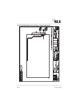
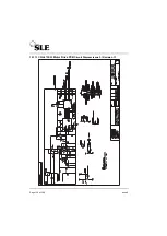
Page 151: ...Issue 8 Page 151 of 286 15 10 1 AS A0739 02 Motor Drive PCB Issue 1 Sheet 2 Revision B ...

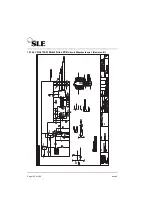
Page 152: ...Page 152 of 286 Issue 8 15 10 2 CD A0739 03 Motor Drive PCB Circuit Diagram Issue 1 Revision B ...

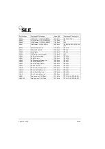
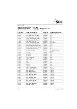
Page 153: ...OL Inverter 1 00 Each U6 D0623 BAX16 Diode 1 00 Each D1 D0624 UF5401 Diode 8 00 Each D2 D9 D0625 L297 1 00 Each U1 D0626 L298N 1 00 Each U2 D0627 RC4152 1 00 Each U3 D0636 TO 251 1 00 Each MOS1 M0228 Heat Sink TO 220 1 00 Each ITEM 3 M0307 Terminal Pin Pcb single sided 1 00 Each TP1 M0309 01 H12 x 20mm Sleeve 1 2mm I D 16 00 Each ITEM 90 M0463 T0220 Transistor Heatsink 2 00 Each ITEM 14 M0680 01 H...

Page 154: ...ylon 7 00 Each ITEM 30 H3091 M3 Nut Full s st 7 00 Each ITEM 26 H2594 M2 5 Shakeproof Washer s st 2 00 Each ITEM 27 H2593 M2 5 Plain Washer s st 2 00 Each ITEM 31 H2595 M2 5 Plain Nylon Washer 2 00 Each ITEM 32 H2591 M2 5 Nut Full s st 4 00 Each ITEM 25 H2316 M2 5 X 16 Pan Hd Pozi s st 2 00 Each ITEM 20 H3110 M3 x 10 Pan Hd Pozi s st 1 00 Each ITEM 21 H3108 M3 x 8 Pan Hd Pozi s st 1 00 Each ITEM 2...

Page 155: ...Issue 8 Page 155 of 286 15 11 AS A0739 02 Motor Drive PCB Issue 2 Revision C ...

Page 156: ...Page 156 of 286 Issue 8 15 11 1 CD A0739 03 Motor Drive PCB Circuit Diagram Issue 3 Revision C ...

Page 157: ...D0402 1N4007 Plastic Diode 3 00 Each D10 D11 D12 in new position D0406 1N4148 1 00 Each D14 D0428 LM7812CT 1 00 Each U4 D0432 LM7805CT 1 00 Each U5 D0601 01 CXA L1OL Inverter 1 00 Each U6 D0623 BAX16 Diode 1 00 Each D1 D0624 5401 Diode 8 00 Each D2 D9 D0625 L297 1 00 Each U1 D0626 L298N 1 00 Each U2 D0627 RC4152 1 00 Each U3 D0636 IRLU110 1 00 Each MOS1 D0651 IN5817 Schottky diode 1 00 Each D13 H2...

Page 158: ...r 1 0 25W SMA0207 2 00 Each R6 R7 R0443 2 2K Resistor 1 0 25W SMA0207 1 00 Each R15 R0451 3 92K Resistor 1 0 25W SMA020 1 00 Each R1 R0460 7 5K Resistor 1 0 25W SMA0207 1 00 Each R16 R0463 10K Resistor 1 0 25W SMA0207 4 00 Each R3 R14 R17 R20 R0469 22 1K Resistor 1 0 25W SMA020 1 00 Each R2 R0486 100K Resistor 1 0 25W SMA0207 1 00 Each R19 R21 1 off added R0641 1R8 Resistor 1 0 25w M Film 8 00 Eac...

Page 159: ...Issue 8 Page 159 of 286 15 12 AS A0756 HFO Start up Motor PCB Issue 1 ...

Page 160: ...ponent Reference s J0756 HFO Start up Motor Mod PCB 1 00 Each Rev A C0485 2 2uf Cap 63 50v 20 2F4 1 00 Each C1 D0406 1N4148 1 00 Each D1 D0627 RC4152N V F F V Converter 0 00 each U3 part of A0739 Assembly D0651 1N5817 Schottky Diode 1 00 Each D2 D0655 BC548c Bipolar Transistor 1 00 Each Q1 R0486 100K Resistor 1 0 25W SMA0207 1 00 Each R1 S0241 01 2 54mm P Std Profile DIL Socket 1 00 Each Socket fo...

Page 161: ...Issue 8 Page 161 of 286 15 13 AS A0738 02 Alarm PCB Assembly ...

Page 162: ...Page 162 of 286 Issue 8 15 13 1 CD A0738 02 Alarm PCB Circuit Diagram ...

Page 163: ... Resistor 1 0 25W SMA0207 8 00 R5 R10 R32 R33 R0445 2K49 Resistor 1 0 25W SMA0207 3 00 R11 R15 R18 R0501 1 0M Resistor 1 0 25W SMA0207 1 00 R12 R0425 332R Resistor 1 0 25W SMA0207 1 00 R13 R0405 10R Resistor 1 0 25W SMA0207 1 00 R14 R0478 45K3 Resistor 1 0 25W SMA0207 1 00 R16 R0436 1 0K Resistor 1 0 25W SMA0207 4 00 R17 R22 R27 R31 R0448 3K16 Resistor 1 0 25W SMA0207 1 00 R19 R0316 820R Resistor ...

Page 164: ...ain Washer s st 2 00 ITEM 30 H3094 M3 Shakeproof Washer s st 2 00 ITEM 40 H3091 M3 Nut Full s st 2 00 ITEM 50 H2106 M2 x 6 Pan Hd Pozi s st 2 00 ITEM 21 H2091 M2 Nut Full s st 2 00 ITEM 51 H2093 M2 Plain Washer s st 2 00 ITEM 31 H2094 M2 Shakeproof Washer s st 2 00 ITEM 41 M0718 Label PCB Identification 1 00 ITEM 17 M0307 Terminal Pin Pcb single sided 34 00 ITEM 8 Part Number Component Description...

Page 165: ...Issue 8 Page 165 of 286 15 14 A0745 01 Pressure Drift Monitor Board ...

Page 166: ...Page 166 of 286 Issue 8 15 14 1 CD A0745 Pressure Drift Board Circuit Diagram ...

Page 167: ...l PCB Identification 1 00 Each N2521 02 Pressure Transducer Calibrated 1 00 Each PTR1 R0268 5K1 Resistor 1 0 25W SMA0207 1 00 Each R1 R0337 3K3 Resistor 1 0 25W SMA0207 1 00 Each R7 R0457 6K8 Resistor 1 0 25W SMA0207 1 00 Each R8 R0463 10K Resistor 1 0 25W SMA0207 1 00 Each R9 R0483 69 8K Resistor 1 0 25W SMA020 1 00 Each R6 R0484 75K Resistor 1 0 25W 3 00 Each R2 R4 R5 S0242 IC Socket 14 way DIL ...

Page 168: ...Page 168 of 286 Issue 8 15 15 A0746 Flow Trigger PCB ...

Page 169: ...CB Blank Rev A 1 00 Each ITEM 1 C0450 0 1uF Capacitor 63V 10 MKS2 1 00 Each C1 D0407 BAT85 2 00 Each D1 D2 D0581 LMC660AIN 1 00 Each U1 M0718 Label PCB Identification 1 00 Each ITEM 3 P0439 5 way 0 10 Pitch MTA Header 1 00 Each J1 R0463 10K Resistor 1 0 25W SMA0207 1 00 Each R1 R0486 100K Resistor 1 0 25W SMA0207 1 00 Each R3 R0602 1k 1 0 5W Resistor MFR4 1 00 Each R2 S0242 IC Socket 14 way DIL 1 ...

Page 170: ...us with HFO NEEP Modification see CD W0317 Wireloom Issue 3 on page 172 Also see SI 000601 Addition of HFO NEEP on page 248 for more information Issue 4 For HFO Plus with new N2125 18 push button swicthes see CD W0317 Wireloom Issue 4 on page 173 Also see SI 060104 Replacement N2125 push button switches on page 270 for more information ...

Page 171: ...Issue 8 Page 171 of 286 15 16 CD W0317 Wireloom Issue 2 A3 version on page 225 of circuit diagram appendix ...

Page 172: ...Page 172 of 286 Issue 8 15 17 CD W0317 Wireloom Issue 3 A3 version on page 227 of circuit diagram appendix ...

Page 173: ...Issue 8 Page 173 of 286 15 18 CD W0317 Wireloom Issue 4 A3 version on page 229 of circuit diagram appendix ...

Page 174: ...Page 174 of 286 Issue 8 15 19 Front Panel ...

Page 175: ...Issue 8 Page 175 of 286 15 20 SK0057 Power Supply Wiring Diagram ...

Page 176: ...Page 176 of 286 Issue 8 15 21 CD W0307 Electronic Pneumatic Module interconnection ...

Page 177: ...Issue 8 Page 177 of 286 15 22 Electronic Chassis S RZ 2000 HFO ...

Page 178: ...Page 178 of 286 Issue 8 ...

Page 179: ...150 grey 4 00 ITEM 7 K0232 Cap blue C150 6 00 ITEM 8 K0233 Collet Knob Cap blue C110 1 00 ITEM 9 K0234 Nut cover with line N151 grey 6 00 ITEM 10 K0235 Nut cover with line N111 grey 4 00 ITEM 11 K0244 Knob SW151 006 Grey 3 00 ITEM 12 K0258 Knob Cap C110 red 3 00 ITEM 13 L0011 60 HFO dampener assembly L0015 Graphic LCD module assy 1 00 ITEM 19 M0211 Trim tool unmodified 1 00 ITEM 20 M0266 Fuse hold...

Page 180: ...0025 Mians plug 13amp 3 pin 1 00 P0025 03 3 amp mains fuse 1 00 P0211 01 Shroud for P0234 3 00 ITEM 42 P0234 Mains filter 1 00 FL1 S0401 25 way D connector socket 1 00 T0209 Knurled Thumb NUt Nylon 66 21 00 ITEM 39 T0934 Terminal cover 1 00 ITEM 41 T0939 Chassis for HFO electronic assy 1 00 ITEM 1 T0942 Window HFO EMC 1 00 T1064 Cover HFO 1 00 ITEM 35 T2019 washer special sponge rubber 3 00 ITEM 3...

Page 181: ...with N2524 60 motor assembly see AS L0263 on page 182 Issue 2 For pnuematic assembly fitted with N2524 61 motor assembly see AS L0263 on page 191 Also see Motor Assemblies on page 29 Issue 3 For pnuematic assembly fitted with HFO NEEP and N2524 61 motor assembly see AS L0263 on page 200 ...

Page 182: ...Page 182 of 286 Issue 8 15 23 Pneumatic Unit Assy AS L0263 15 23 1 AS L0263 Sheet 1 of 4 Issue 1 For ventilator with SLE part Nº N2524 60 motor assembly ...

Page 183: ...Issue 8 Page 183 of 286 15 23 2 AS L0263 Sheet 2 of 4 For ventilator with SLE part Nº N2524 60 motor assembly ...

Page 184: ...Page 184 of 286 Issue 8 15 23 3 AS L0263 Sheet 3 of 4 For ventilator with SLE part Nº N2524 60 motor assembly ...

Page 185: ...Issue 8 Page 185 of 286 15 23 4 AS L0263 Sheet 4 of 4 For ventilator with SLE part Nº N2524 60 motor assembly ...

Page 186: ...EM 8B N2184 64 INSP Pressure Gauge 4 bar 1 00 Each ITEM 8C N2191 Oxygen Cell Sensor SLE2000 1 00 Each Drg Sht 1 ITEM 40 N2195 04 Solenoid Valve 3 0mm c w Plug 1 00 Each Drg Sht 1 ITEM 60 T0249 Volume Chamber Assy 1 00 Each Drg Sht 1 ITEM 50 W0307 Wiring Loom HFO CE Pneumatic 1 00 Each Drg Sht l ITEM 51b Part Number Component Description Used Unit Component Reference s H8091 M8 Nut Full s st 1 00 E...

Page 187: ... Sht 1 ITEM 1 T0243 Spacer solenoid 10 00 Each Drg Sht 1 ITEM 29 T0250 Latch Block Finish Anodised 1 00 Each Drg Sht 1 ITEM 18 T0251 Hinge Pins Short 1 00 Each Drg Sht 1 ITEM 20 T0252 Catch Piece Finish Anodised 1 00 Each Drg Sht 1 ITEM 19 T0614 Cover fixed side with fan 1 00 Each Drg Sht 1 ITEM 5 T0616 01 Block fixing Item 2 1 00 Each Drg Sht 1 ITEM 24 T0617 Block fixing small end 1 00 Each Drg S...

Page 188: ...87 Spacer HFO PLUS x 30mm Long 2 00 Each Drg Sht 2 ITEM 10 T1087 01 Spacer HFO PLUS x 59mm Long 3 00 Each Drg Sht 2 ITEM 9 T1105 Relief Valve Block HFO PLUS 1 00 Each Drg Sht 2 ITEM 20 T1110 Blocking Piece HFO PLUS 1 00 Each Drg Sht 2 ITEM 14 M0434 Cable Tie Electrical use 4 00 Each Drg Sht 4 ITEM 30 M0700 Hose clip dia 6 5 8 2mm black 2 00 Each Drg Sht 4 ITEM 35 N2030 Tygon Tubing 1 8 x 1 4 1 80 ...

Page 189: ...94 Steady Washer PTFE HF0 PLUS 1 00 Each Drg Sht 4 ITEM 33 M0673 01 Dome Plug Dia 25 4 PAINTED 1 00 Each ITEM 13 M0751 PTFE Tape x 12mm Wide 12M Roll 0 05 Each H3091 M3 Nut Full s st 30 00 Each Drg Sht 3 ITEM 16 Sht 1 ITEM 48 3 off H3094 M3 S Proof Washer s st DIN6798 41 00 Each Drg Sht 3 ITEM 17 H3095 M3 Plain Washer Nylon 11 00 Each Drg Sht 3 ITEM 18 H3108 M3 x 8 Pan Hd Pozi s st 8 00 Each Drg S...

Page 190: ...ch Drg Sht 3 ITEM 19 H4110 M4 x 10 Pan Hd Pozi s st 1 00 Each Drg Sht 3 ITEM 21 H9608 M3 x 8 Button Hd Socket s st 5 00 Each Drg Sht 3 ITEM 15 H9710 M4 x 10 Button Hd Socket s st 2 00 Each Drg Sht 3 ITEM 22 H5091 M5 Nut Full s st 1 00 Each Drg Sht 4 ITEM 16 Part Number Component Description Used Unit Component Reference s ...

Page 191: ...Issue 8 Page 191 of 286 15 23 5 AS L0263 Sheet 1 of 4 Issue 2 For ventilator with SLE part Nº N2524 61 motor assembly ...

Page 192: ...Page 192 of 286 Issue 8 15 23 6 AS L0263 Sheet 2 of 4 For ventilator with SLE part Nº N2524 61 motor assembly ...

Page 193: ...Issue 8 Page 193 of 286 15 23 7 AS L0263 Sheet 3 of 4 For ventilator with SLE part Nº N2524 61 motor assembly ...

Page 194: ...Page 194 of 286 Issue 8 15 23 8 AS L0263 Sheet 4 of 4 For ventilator with SLE part Nº N2524 61 motor assembly For ventilator with SLE part Nº N2524 61 motor assembly See Motor Assemblies on page 29 ...

Page 195: ...ure Gauge 4 bar 1 00 Each ITEM 8C N2191 Oxygen Cell Sensor SLE2000 1 00 Each Drg Sht 1 ITEM 40 N2195 04 Solenoid Valve 3 0mm c w Plug 1 00 Each Drg Sht 1 ITEM 60 T0249 Volume Chamber Assy 1 00 Each Drg Sht 1 ITEM 50 W0307 Wiring Loom HFO CE Pneumatic 1 00 Each Drg Sht l ITEM 51b Part Number Component Description Used Unit Component Reference s H8091 M8 Nut Full s st 1 00 Each Drg Sht 1 ITEM 16 M03...

Page 196: ...lock cross 1 00 Each Drg Sht 1 ITEM 2 T0236 Fixing Block end 1 00 Each Drg Sht 1 ITEM 3 T0237 Fixing block small end 1 00 Each Drg Sht 1 ITEM 1 T0243 Spacer solenoid 10 00 Each Drg Sht 1 ITEM 29 T0250 Latch Block Finish Anodised 1 00 Each Drg Sht 1 ITEM 18 T0251 Hinge Pins Short 1 00 Each Drg Sht 1 ITEM 20 T0252 Catch Piece Finish Anodised 1 00 Each Drg Sht 1 ITEM 19 T0614 Cover fixed side with fa...

Page 197: ... T1083 Inner Partition HFO PLUS 1 00 Eaeh Drg Sht 2 ITEM 2 T1084 32T Pulley for HFO PLUS 1 00 Eaeh Drg Sht 2 ITEM 11 T1085 Outer Partition HFO PLUS 1 00 Each Drg Sht 2 ITEM 1 T1087 Spacer HFO PLUS x 30mm Long 2 00 Each Drg Sht 2 ITEM 10 T1087 01 Spacer HFO PLUS x 59mm Long 3 00 Each Drg Sht 2 ITEM 9 T1105 Relief Valve Block HFO PLUS 1 00 Each Drg Sht 2 ITEM 20 T1110 Blocking Piece HFO PLUS 1 00 Ea...

Page 198: ... Sht 4 ITEM 11 T0626 Banjo Tee Blender output 1 05 iach Drg Sht 4 IISM 9 T0628 Banjo bolt 1 00 Each Drg Sht 4 ITEM 10 T1093 Special Elbow HFO PLUS 1 00 Each Drg Sht 4 ITEM 32 T1094 Steady Washer PTFE HF0 PLUS 1 00 Each Drg Sht 4 ITEM 33 M0673 01 Dome Plug Dia 25 4 PAINTED 1 00 Each ITEM 13 M0751 PTFE Tape x 12mm Wide 12M Roll 0 05 Each H3091 M3 Nut Full s st 30 00 Each Drg Sht 3 ITEM 16 Sht 1 ITEM...

Page 199: ...akeproof Washer s st 3 00 Each Drg Sht 3 ITEM 24 H4108 M4 x 8 Pan Hd Pozi s st 1 00 Each Drg Sht 3 ITEM 19 H4110 M4 x 10 Pan Hd Pozi s st 1 00 Each Drg Sht 3 ITEM 21 H9608 M3 x 8 Button Hd Socket s st 5 00 Each Drg Sht 3 ITEM 15 H9710 M4 x 10 Button Hd Socket s st 2 00 Each Drg Sht 3 ITEM 22 H5091 M5 Nut Full s st 1 00 Each Drg Sht 4 ITEM 16 Part Number Component Description Used Unit Component Re...

Page 200: ...Page 200 of 286 Issue 8 15 23 9 AS L0263 Sheet 1 of 4 Issue 3 For pneumatic unit with HFO NEEP ...

Page 201: ...Issue 8 Page 201 of 286 15 23 10 AS L0263 Sheet 2 of 4 For ventilator with SLE part Nº N2524 61 motor assembly ...

Page 202: ...Page 202 of 286 Issue 8 15 23 11 AS L0263 Sheet 3 of 4 For ventilator with SLE part Nº N2524 61 motor assembly ...

Page 203: ...Issue 8 Page 203 of 286 15 23 12 AS L0263 Sheet 4 of 4 For ventilator with SLE part Nº N2524 61 motor assembly ...

Page 204: ...1 ITEM 22 N2184 62 CPAP PEEP Pressure Gauge 4 bar 1 00 Each ITEM 8A N2184 63 OSC Pressure Gauge 0 lOOcm 1 00 Each ITEM 8B N2184 64 INSP Pressure Gauge 4 bar 1 00 Each ITEM 8C N2191 Oxygen Cell Sensor SLE2000 1 00 Each Drg Sht 1 ITEM 40 N2195 04 Solenoid Valve 3 0mm c w Plug 1 00 Each Drg Sht 1 ITEM 60 T0249 Volume Chamber Assy 1 00 Each Drg Sht 1 ITEM 50 W0307 01 Loom HFO Pneumatic NEEP SV4 1 00 E...

Page 205: ...egulator Bracket 1 00 Each Drg Sht 1 T0224 Captive Nut 2 00 Each Drg Sht 1 T0226 Analyser Base 1 00 Each Drg Sht 1 T0228 Analyser block 1 00 Each Drg Sht 1 T0229 Vent Screw 1 00 Each Drg Sht 1 T0230 Analyzer Connector 1 00 Each Drg Sht 1 T0232 Blender Bracket 1 00 Each Drg Sht 1 T0233 Clamp Block 2 00 Each Drg Sht 1 T0235 Fixing Block cross 1 00 Each Drg Sht 1 T0236 Fixing Block end 1 00 Each Drg ...

Page 206: ... N2194 Relief Valve Series 500 1 00 Each Drg Sht 2 T0240 Relief Valve Cover 1 00 Each Drg Sht 2 T0612 Spacer flanged 4 00 Each Drg Sht 2 T0613 01 Spacer M3 round bar x 59mm long 3 00 Each Drg Sht 2 T0618 Block connector R A 1 00 Each Drg Sht 2 T0619 Plate Motor 1 00 Each Drg Sht 2 T0826 Label l9X40mm To Drg 100826 A 2 00 Eaeh Drg Sht 2 Sht 4 T1083 Inner Partition HFO PLUS 1 00 Eaeh Drg Sht 2 T1084...

Page 207: ...M5 Aluminium Washer No 411 M5 58 00 Each Drg Sht 4 ITEM 4 N2372 Polyurethane Tubing APU 5 3 CL 4 70 Metre Drg Sht 4 ITEM 19 N2373 Polyurethane Tubing 6 4 APU 0 50 Metre Drg Sht 4 ITEM 20 N2514 1420 6 4 1 8 Tee 1 00 Each Drg Sht 4 ITEM 37 N2515 Nipple M5 miniature 1 00 Each Drg Sht 4 ITEM 38 N2516 Reducing bush 1 00 Each Drg Sht 4 ITEM 39 T0280 01 Washer seal I D 4 9 O D 9 5 2 00 Each Drg Sht 4 ITE...

Page 208: ...20 Csk Hd Pozi s st 2 00 Each Drg Sht 3 ITEM 13 H3225 M3 x 25 Csk Hd Pozi s st 3 00 Each Drg Sht 3 ITEM 14 H4010 M4 x 10 Hex Hd St Stl Screw 1 00 Each Drg Sht 3 ITEM 20 H4091 M4 Nut Full s st 3 00 Each Drg Sht 3 ITEM 23 H4094 M4 Shakeproof Washer s st 3 00 Each Drg Sht 3 ITEM 24 H4108 M4 x 8 Pan Hd Pozi s st 1 00 Each Drg Sht 3 ITEM 19 H4110 M4 x 10 Pan Hd Pozi s st 1 00 Each Drg Sht 3 ITEM 21 H41...

Page 209: ...Issue 8 Page 209 of 286 16 A3 Circuit Diagram Appendix A3 circuit Diagram Appendix ...

Page 210: ...Page 210 of 286 Issue 8 This page is intentionally blank ...

Page 211: ...Issue 8 Page 211 of 286 CD A0702 05 Issue 2 ...

Page 212: ...Page 212 of 284 ...

Page 213: ...Issue 8 Page 213 of 286 CD A0702 05 Issue 3 ...

Page 214: ...Page 214 of 284 ...

Page 215: ...Issue 8 Page 215 of 286 CD A0702 05 Issue 4 ...

Page 216: ...Page 216 of 284 ...

Page 217: ...Issue 8 Page 217 of 286 Main PCB Circuit Diagram For Rev E Board This section of board is not used ...

Page 218: ...Page 218 of 284 ...

Page 219: ...Issue 8 Page 219 of 286 Main PCB Circuit Diagram For Rev F Board Issue 2 This section of board is not used ...

Page 220: ...Page 220 of 284 ...

Page 221: ...Issue 8 Page 221 of 286 Main PCB Circuit Diagram For Rev F Board Issue 3 This section of board is not used ...

Page 222: ...Page 222 of 284 ...

Page 223: ...Issue 8 Page 223 of 286 Main PCB Circuit Diagram For Rev F Board Issue 4 This section of board is not used ...

Page 224: ...Page 224 of 284 ...

Page 225: ...Issue 8 Page 225 of 286 CD W0317 Issue 2 Wireloom Diagram ...

Page 226: ...Page 226 of 284 ...

Page 227: ...Issue 8 Page 227 of 286 CD W0317 Issue 3 Wireloom Diagram ...

Page 228: ...Page 228 of 284 ...

Page 229: ...Issue 8 Page 229 of 286 CD W0317 Issue 4 Wireloom Diagram ...

Page 230: ...Page 230 of 284 ...

Page 231: ...Issue 8 Page 231 of 286 Service Information and Technical Bulletins ...

Page 232: ...e 236 SI 990801 Enhanced EMC See page 238 SI 000101 Modification of SLE 2000 HFO motor drive circuit board See page 243 SI 000201 Leak Alarm Trigger Threshold See page 246 SI 000601 Addition of HFO NEEP See page 248 SI 020901 Cleaning Disinfection and Sterilisation of SLE ventilators See page 269 SI 060104 Replacement N2125 push button switches See page 270 Technical Bulletins TB 000201 New versio...

Page 233: ...x 60 to 60cmH2O Adjust RV3 until the voltage measured at DIFF is the same at 60cmH2O as it is at 60cmH2O to within 20mV DIFF should be in the region of 8V Pay special attention to the indicated polarities when measuring voltages b Set the DC voltage between HIGH and LOW to 180mV 5mV using RV2 c Set the DC voltage between HIGH and DIFF to 90mV 5mV using RV1 d Repeat steps b and c until both voltage...

Page 234: ...essure Drift Board How to verify the Pressure Drift Detection Using a short length of 1 8 Tygon connect a 2ml syringe to port P1 on pressure transducer PTR1 on the A702 board Monitor the digital pressure display with the pressure display switch in the MIN position 1 Using the syringe adjust the pressure to 6cmH2O and hold for several seconds ensuring that the pressure drift detection warning is di...

Page 235: ...R34 with its cathode ve connected to the drain of Q4 IRLU110 on all A0702 boards Additionally if the ventilator is an SLE2000 then change R32 to 8k2 and R34 to 91k 0 25W 1 Metal Film Rationale The diode will be reverse biassed when Q4 is turned off When Q4 is turned on it has a value of Rds of 0 5W giving a Vds of 0 1v The diode voltage is added to this which shall result in the microcontroller i ...

Page 236: ...d on the silk screen All units manufactured to date and currently in service have passed their final test and were functional on leaving the factory There is no reason to suppose that any of the operating parameters for this circuit would have changed or that device failure would have occured since the reverse configuration does not have the potential to damage the components Therefore units in th...

Page 237: ...tch the mode to CPAP and check the operation of the 12V supply supply monitor by ensuring that the battery alarm sounds Turn of the vent reconnect the 24V line and disconnect the 12V line from the PSU pin 9 on J2 Switch the mode to CPAP and check the operation of the 12V supply monitor by ensuring that the battery alarm sounds again Reconnect the 12V line ...

Page 238: ...SLE part No D0714 Remove U6 and U14 Cut track from pin 31 of U14 socket as shown fig 1 Link pins 31 and 40 of U14 as shown fig 2 SLE part No W0103 Link pins 13 of U18 and 0v as shown fig 2 SLE part No W0103 Fit 100pF ceramic Capacitor as shown fig 2 SLE part No C0404 Link C7 0v pin to U7 pin4 as shown fig 2 SLE part No W0103 Fit U14 ATMEL 89C55 33PC with Firmware as follows SLE part No D0710 The s...

Page 239: ...x Ferrite Sleeve on to Slider Rail as shown figs 4a and 4b using Cable TieSLE part No M0856 Motor Drive PCB A0739 01 02 03 HFO non CE HFO CE HFO Cut PCB track at 8 points as shown fig 5 Fit 100nF Capacitor from pin 4 to pin 8 of U3 as shown fig 5 SLE part No C0481 Fit 1nF Capacitor from pin 2 to pin 18 of U1 shown fig 5 SLE part No C0490 Link R4 0v to pin 18 of U1 as shown fig 5 SLE part No W0103 ...

Page 240: ...Page 240 of 286 Issue 8 Figure 1 Figure 2 U14 U18 U7 Solder to PCB at these points Figure 3 ...

Page 241: ...Issue 8 Page 241 of 286 Figure 4b ...

Page 242: ...the modifications and confirm that they have been carried out in full accord ance with the above procedure After reassembly ensure that the ventilator is fully operational in accordance with its test schedule Figure 5 CUT TRACK IN 8 PLACES U1 U3 U8 U6 Vin U6 0v ...

Page 243: ...f customer complaint Equipment Required General hand tools and DIL IC Extractor Additional Parts Circuit board SLE Part Nº J0756 Warnings and Cautions All work should be carried out by a suitably qualified engineer Anti static precautions have to be observed when handling the printed circuit boards Modification Detail 1 Remove ventilator covers Remove the motor drive board from the ventilator taki...

Page 244: ...Page 244 of 286 Issue 8 2 Remove the integrated circuit from the motor drive board at position U3 3 Insert into the connector the circuit board supplied Note the orientation of this board ...

Page 245: ...ector is plugged securely into it s socket before pushing board back into its socket Fit thumb retaining screw Refit covers Testing Connect power gases and patient circuit Switch ON ventilator Check all ventilator basic functions Set HFO frequency control to maximum Switch ON HFO mode and check motor starts and runs correctly Repeat this test three times Check that motor speed can be varied by usi...

Page 246: ...or has been added across the input of U500A Pins 2 3 on the A0702 Board See photograph and circuit diagram This capacitor is being added as standard to all new production and it is recommended that this modification should be carried out during routine servicing The capacitor used is a 100nf multilayer palladium ceramic type and can be order from SLE using part Nº C0481 Alternatively it can be ord...

Page 247: ...Issue 8 Page 247 of 286 100nf ...

Page 248: ...ns All work should be carried out by a suitably qualified engineer with experience of the SLE 2000 HFO ventilator All swarf and foreign matter has to be removed from the interior of the ventilator before being returned to service The ventilator has to be checked and certified as functioning correctly before being returned to service The ventilator has to be labelled to show that it has been modifi...

Page 249: ...ove the exhalation block and any filters 2 Remove the two screws 1 from the rear of the ventilator 3 Remove two screws 2 from the base of unit Warning take care not to undo the ventilator pole fixing screws A as this may cause the ven tilator to fall from the stand 4 Lift the complete unit from stand 5 The unit can then be placed on the work surface upside down Assembly is the reversal of removal ...

Page 250: ...ascertain which motor assembly is fitted to your ventilator The method of identifying which motor assembly is fitted is as follows The N2524 60 motor assembly is connected to the ventilator via a 9 pin D connector See photograph A The N2524 61 motor assembly is connected to the ventilator via a 8 way Molex connector See photograph B Photograph A Photograph B N2524 60 Motor assembly N2524 61 Motor ...

Page 251: ...pin D connector and unplug connector Removal of N2524 61 motor assembly B Unplug 8 way Molex connector 2 and release the rubber grommet 3 from the slot The disassembly is the now the same for both motor assemblies 1 Remove the screw and washer 4 from the solenoid support strap 5 1 1 2 3 4 5 ...

Page 252: ...r 7 Remove the volume chamber and clip from the pneumatic unit 3 Remove the screws and washers 9 from the solenoid support bracket 10 Remove the bracket from the pneumatic unit 4 Remove the screws and washers 11 from the solenoid support strap 5 Remove the support strap from the pneumatic unit 8 7 6 9 9 9 9 10 11 11 11 11 11 11 5 ...

Page 253: ...from the SV4 solenoid 14 7 Remove the fresh gas relief valve tube 15 by cutting cable tie 16 and easing the tube off the connector 8 Remove the NEEP tube 17 by unscrewing the retaining nut 18 from the pneumatic connector Disconnect the remaining tube not shown to the NEEP adjusting block and remove from the pneumatic unit 12 13 14 15 16 18 17 ...

Page 254: ...uring the orifice block 12 Remove the three screws and shake proof washers 22 retaining the motor assembly 13 Remove the sub assembly by tilting the top towards you Step 3 Modification of motor assemblies The following step is applicable to both motor assemblies Drill two 4 5mm holes in the positions indicated in the diagram below 19 20 21 21 22 22 22 68mm 19mm Ø4 5mm 20mm ...

Page 255: ...dification Kit on page 267 2 Connectors N2362 and N2363 are re used from the old NEEP adjusting block 3 Attach the shuttle valve using screws H4125 washers H4094 and nuts H4091 at position A 4 At this stage attach the new NEEP tube length 140mm to the lower connector B on the shuttle valve This allows for easier assembly later N2361 64 N2360 64 N2517 N2516 N2515 N2362 existing N2363 existing T1103...

Page 256: ...the loom by removing the electrical connectors 2 3 Discard the solenoid SV4 3 4 To allow the new SV4 solenoid to fit the SV3 solenoids body 4 has to be rotated through 180º 5 Remove the electrical connectors 5 from the SV3 solenoid 6 Slacken the nut 6 at the base of the SV3 solenoid valve 2 3 4 4 5 4 4 3 1 2 2 2 3 4 4 5 4 4 4 5 5 2 3 4 4 5 4 4 6 ...

Page 257: ...sing a small screw driver 10 You now need to insert the rubber grommets M0402 and the spacers T0243 into the new support strap T0992 A Install the 8 rubber grommets and spacers in the following positions indicated in the photograph B To install the spacers use the following procedure C Assemble a M3 screw nut and two washers not supplied with the spacer in the configuration shown in the photograph...

Page 258: ...the grommet squarely E Remove the screw washers and nut leaving the grommet and spacer in place Repeat the process for all the other indicated holes 11 Assemble the Shuttle Valve and NEEP assembly as indicated in the diagram below using the parts from section B of the modification kit on page 267 N2195 17 N2360 64 N2180 01 N2514 ...

Page 259: ...ws spacers and valve 13 The solenoid is now ready to be re fitted to the ventilator Note the photograph shows the port identification letters of the solenoid valve R Blanking plug A Tee connector Connection SV4 to HFO jet SV4 to shuttle valve 90º elbow connector P 90º Elbow connector Connection SV4 to SV5 Screw H3140 Washer Nylon H3095 Spacer Nylon M0305 03 Shake proof washer H3094 Nut H3140 Valve...

Page 260: ...ve has to be modified to accept the smaller electrical contact prongs A Remove the existing tab connectors from the two wires B Strip back plastic sleeve to reveal bare wire C Thread through insulation cover D Crimp new connectors to wire using the appropriate crimping tool E Cover the connector with the insulation cover ...

Page 261: ...existing pneumatic tube The tube will have to be trimmed so it does not kink 8 Connect the remaining SV4 tee outlet Port A 4 to the shuttle valves side connector using the new section of tubing 280mm length supplied with the modification kit 9 Reconnect the SV3 pneumatic tube to the side connector of the NEEP adjustment block 10 Reconnect the 5 way block pneumatic tube to the bottom connector of t...

Page 262: ...Page 262 of 286 Issue 8 Pneumatic Schematic ...

Page 263: ...l out the hole 5 Carry out an operational check of the ventilator Verify that A Inadvertent mean pressure is less than 5cmH2O but NOT negative for all HFO Delta pressures B Set CPAP mode with HFO off and 15 LPM fresh gas flow Adjust the NEEP Block so inadvertent PEEP is 0 0cmH2O to 1 0cmH2O at 15 LPM fresh gas 6 If the above criteria has not been met repeat step 4 to 5 in stages of 0 05mm Continue...

Page 264: ... Step 9 Modification of A0736 PCB 1 Cut track from U21 8 to U21 9 and U21 9 to U21 10 Link from U21 8 to U21 10 use W0103 red link wire 2 Add 100 K W SLE Part Nº R0486 resistor from PLA 32a to PLA 27a 100K Track side T3 Base ...

Page 265: ... component side of the board Drill two holes to accommodate the resistor Make sure that you do not cut any of the tracks on the reverse side of the board The location of the resistor is indicated opposite 4 Link from PLA27a to U21 9 5 Change R48 from 1 K W to 10K W SLE Part Nº R0463 R48 Drill holes in this area Component Side T3 U21 10K ...

Page 266: ...1 02 Step 11 Final Check 1 Carry out a final operational check and verify that the ventilator is working correctly Note That HFO oscillation is now disabled on a high alarm condition 2 Label the ventilator to show it has been modified for HFO NEEP 3 Return the ventilator to service 100K PLA32a PLA27a R48 10K 10K 10 ...

Page 267: ...le Stud Coupling 1 00 Connects to shuttle valve Out N2517 Shuttle Valve G1 8 1 00 Fit to existing 4mm dia hole previously for T1103 on inner partition near edge N2516 Reducing Bush M5F to 1 8 Male 1 00 T1103 NEEP adjusting block 1 00 Issue 2 block N2515 Nipple M5 Miniature 1 00 Connects Neep Jet Block to Shuttle Valve with item below Part Nº Component description Quantity Note N2195 17 24vDC Inter...

Page 268: ...6 3 tab connectors on loom M0783 03 Insulation Cover 2 8 2 00 N2515 Nipple M5 Miniature 1 00 Connects existing Neep Jet Block to Shuttle Valve with item below H4125 M4 x 25 Pan Hd Pozi s st 2 00 Secures shuttle valve to partition H4091 M4 Nut Full s st 2 00 H4094 M4 Shake proof Washer s st 2 00 M0402 Rubber grommets 8 00 For new support strap N2373 Polyurethane Tubing 6 4 APU 280 mm SV4 to shuttle...

Page 269: ...e medical devices are required to provide information on how to decontaminate their devices This information should include the types of decontamination agent that may be used together with a warning of any agents or processes that are known to be detrimental to the device Due to SN 2001 28 we are issuing more detailed guidelines for the Cleaning Disinfection and Sterilisation of our products to b...

Page 270: ...mprise of the complete switch and lens plus instructions of fitment Details of the part numbers are listed in the ordering information section of the letter The new 18 switches are wired into the loom differently and as such the user has to take note of the following information Installation instructions for 18 switches Step 1 Gain access to the rear of the front panel of the ventilator Step 2 Pul...

Page 271: ...1 and PB3 use N2128 04 18 switch PB2 use N2128 02 18 switch SLE2000 HFO HFO SW2 SW3 and SW8 use N2128 04 18 switch SW10 use N2128 02 18 switch Step 9 Cover the soldered joints with the existing sleeve Ordering information To order replacement switches please use the following service part numbers Red illuminated push button switch N2128 02 18 Yellow push button switch N2128 04 18 ...

Page 272: ...ine triggered breaths Breaths are still indicated by the trigger back up LED illuminating If required the audible bleep can be re instated by holding in the reset button when powering up the ventilator The above feature is available from the following software versions Subject New versions of control software Equipment SLE 2000 SLE 2000 HFO and SLE 2000 HFO Ventilators Serial Numbers All Technical...

Page 273: ...7 06 94 Changed I E Ratio display from flashing to non flashing hyphens if ratio 1 9 9 or 9 9 1 V3 3 15 01 99 CN0616 No audible indication of machine triggered breaths in patient triggered modes SIMV and PTV unless reset button is held in during power up Firmware version Date of change Change note Nº Details of change V1 09 09 03 93 Flashing of I E Ratio display replaced with hyphens to indicate o...

Page 274: ...ction which caused erroneous triggering at low pressures V1 5 26 03 96 CN0116 Delta P to be displayed for CPAP and HFO modes and ident on oscillator pressure gauge changed V1 6 10 07 96 CN0156 Increased range of display of delta pressures Addition of display of pressure transducer saturation positive and negative V1 7 30 04 97 CN0308 Implementation of an HFO disconnection alarm and pressure transd...

Page 275: ...ation of machine triggered breaths in patient triggered modes SIMV and PTV V1 20 22 10 99 CN0676 Change to the averaging period of the mean calculation to 4 seconds Watchdog servicing time changed from 350ms to 20ms Firmware version Date of change Change note Nº Details of change V1 0 30 09 98 CN0560 Initial release V1 1 08 12 98 CN0589 Removal of mean pressure drop alarm High delta P converted to...

Page 276: ...o the patient However when ventilating a patient with a 3mm or smaller size endotracheal tubes in case of patient extubation or the ET tube disconnecting from its ET connector only the monitoring of flow module SLE 2100 or of SpO2 or PtO2 PtCO2 will dependably alert the medical team to an alarm situation not the monitoring of pressures New operational warning 2 The SLE2000 HFO is a more powerful v...

Page 277: ...N 0983 Date 05 04 2004 Introduction This technical bulletin is to inform the users of the SLE2000 SLE2000 HFO SLE2000 HFO Infant ventilators that the design of the V0226 potentiometer has changed The potentiometer has changed from a Spectrol 149SXN48S103SP to a Spectrol 149SXN40S103SP 149SXN48S103SP 149SXN40S103SP The change in design requires that the 149SXN40S103SP is fitted with two shake proof...

Page 278: ...block Combined with ventilating a patient with oxygen rich gas the following illustrates unintended fault conditions that may cause gas to leak from the jet orifices in the exhalation block hence increasing the oxygen concentration in air surrounding the jet belt and motor For a leak to be serious it would be of a magnitude that it is clearly audible by ear Worn damaged o ring seals and obstructed...

Page 279: ...t is recommended that the jet nozzle o rings be replaced every 6 months If in doubt whether a motor assembly could have been subjected to prolonged high oxygen exposure and has potentially aged prematurely due to any of the conditions described above then check for Drive belt does not show signs of shedding debris black dust and Motor does not emit unusual sounds or does not feels smooth running I...

Page 280: ...Issue 8 Page 280 of 286 18 Issue Revision Record Issue 1 Initial issue Issue 2 CN 0764 Issue 3 CN 0738 Issue 4 CN 0798 Issue 5 CN 0921 CN 1001 CN 1005 CN 1022 Issue 6 CN 1134 Issue 7 CN 1208 ...

Page 281: ...ssure Range 69 Display screen 13 Display Timebase 69 Display Board 100 Displayed Faults 78 E Electronic Pneumatic Module interconnection 176 Exchanging a Pneumatic Unit 46 Exhalation block 13 F Fan Alarm 77 Fan and Filter 14 FAN Fail 69 Fan Fail 56 Filter only 14 FIO2 Adjustment Tool 14 FIO2 Calibration adjustment 14 Fixed jet 15 Flow Trigger PCB 168 Flow trigger switch 13 Freeze Push Button 69 Fr...

Page 282: ...ESSURE 78 Pneumatic Unit 181 Power on and mode switch 13 Power Supply Unit 49 Power Supply Wiring Diagram 175 Pressure Controls 71 Pressure Drift Monitor Board 165 Pressure wave selector switch 13 Principles of Operation 10 Product information plate 14 PTV Mode 70 PTV sensitivity control 13 R Recommended equipment 48 Reset button 13 Rotating jet 15 routine maintenance 10 RT200 Calibration Analyser...

Page 283: ...e 8 Page 283 of 286 232 273 TB 010201 276 TB 040401 277 TB051101 278 Technical Bulletins 232 test point 18 19 Time control switch 13 Troubleshooting 76 V Verifying Pressure Drift Detection 72 W Wireloom 170 ...

Page 284: ...Page 284 of 286 Issue 8 This page is intentionally blank ...

Page 285: ...Issue 8 Page 285 of 286 SLE reserves the right to make changes without prior notice in equipment publications and prices as may be deemed necessary or desirable ...

Page 286: ......
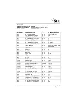
Reviews: