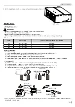
32
Installation Manual
● Before starting work, check that power is not being supplied to the outdoor unit.
● Match the terminal block numbers and connection cord colors with those of the indoor unit side.
● Erroneous wiring may cause burning of the electric parts.
● Connect the connection cords firmly to the terminal block. Imperfect installation may cause a fire.
● Always fasten the outside covering of the connection cord with cord clamps. (If the insulator is not clamped, electric leakage may occur.)
● Always connect the ground wire.
CAUTION!
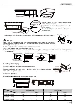
4. Wiring of the Power Cord
Refer to the Installation Manual of the wired controller for more details.
The power supply for each indoor unit must be uniform.
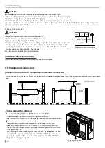
● Dismantle the cover of the electric box of the indoor unit.
● Let the power cord go through the rubber ring.
● Connect the wiring (communication) through the piping hole of the chassis and the bottom of
the appliance upward, then connect the brown wire to the terminal board “3”; black wire(the
communication wire) to the terminal board “2”; blue wire to the box. Clamp them with the
corresponding wire clamp packed in the chassis.
● Fix the power cord tightly with the binding wire.
CAUTION!
blue
yellow-
green
Outdoor unit connection
black brown
3
2
N(1)
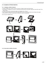
Installation of the Wired Controller
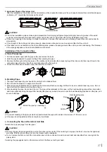
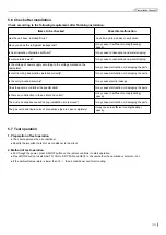
Fix the support of outdoor
Select it according to the actual installation situation
1. Select installation location according to the house structure.
2. Fix the support of outdoor unit on the selected location with expansion screws.
Note:
● Take sufficient protecttive measures when installing the outdoor unit.
● Make sure the support can withstand at least four times of the unit weight.
● The outdoor unit should be installed at least 3cm above the the floor in order
to install drain joint.
● For the unit with cooling capacity of 2300W~5000W, 6 expansion screws are
needed; for the unit with cooling capacity of 6000W~8000W, 8 expansion
screws are needed; for the unit with cooling capacity of 10000W~16000W,
10 expansion screws are needed.
at least 3cm above
the the floor
5.5 Installation Outdoor Unit
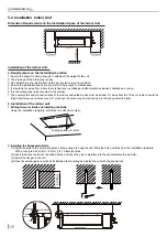
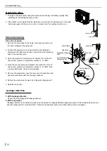
Dimension Requirements on the Installation Space of the Outdoor Unit
>
500
>
50
0
>
500
>
500
>
2000
>
2000
>
1000
Units: mm
Provide the space, so that the air flow is not blocked.Also for efficien operation, leave three of four directions of peripheral constructions
open.

