


11
Operator’s Manual -
Model
NXG-4650
TV I
nsTallaTIon
& C
onneCTIons
|
Rear Panel Component Source
WARNING: Do not connect the power source before making connections.
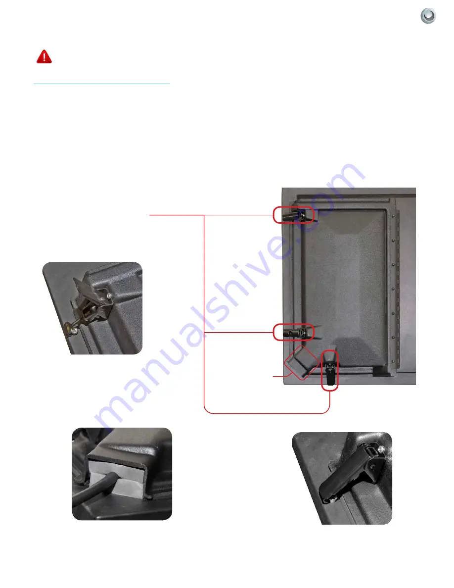
Internal Component Source
The Internal Component Source allows you to easily connect to the Audio, Video, Digital Audio Out, HDMI, Audio
Out, and RF connectors.
1. The Internal Component Source is inside the Component Cover located on the back of the unit.
2. Open the 3 latches located on the back cover of your SkyVue TV , and pull the cover towards you.
3. Route cables to the proper inputs, and place the cable cords over the Rubber Sealing Gasket.
4. Close the cover.
5. Press firmly on the cover, and secure the hinged latches.
Component Cover Latches
CABLE PASSAGE
OPEN LATCH
CLOSED LATCH
CABLE PASSAGE


