background image

37

Owner’s Manual  - 

Model

 NXG-5570-DS | C-NXG-5570-DS

A

djusting

 O

n

-s

creen

 d

isplAys

Advanced Selection Services

When the CC Mode submenu is on-screen, press 
the 


 buttons to highlight Advanced Selection 

Services. Use  


 to select Advanced Selec-

tion Services Off or 1-6. Availability of these 
services depends on the TV program.

Options

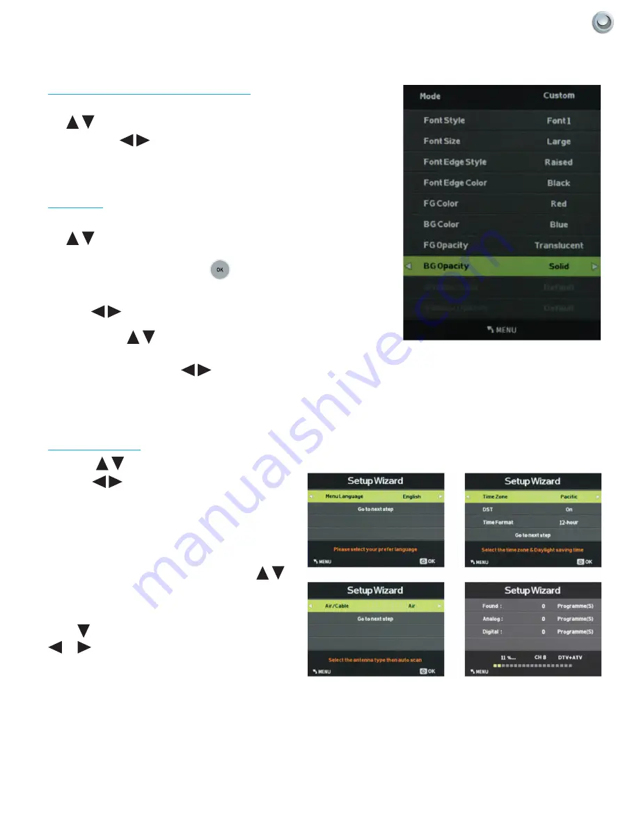
When the CC Mode submenu is on-screen, press 
the 


 buttons to highlight Options. This option 

is available only when one of the Advanced Selec-
tion Services is selected. Use the 

 button to 

enter the Options submenu shown at left. 

Now the 


 will allow you to select Default or 

Custom mode for the captions. In Custom Mode, 
you can use the 


 buttons to select different 

options, such as font style and size, font color and 
background color, then use 


 to adjust these 

options.

Setup Wizard

Press the 


 buttons to highlight Setup Wizard, 

then use 


 to start the Setup Wizard. You will 

see the first of four submenus, all of which are 
shown at left. The Setup Wizard will take you 
quickly through several basic settings on the TV, 
including Menu Language, Time Zone, DST on/off, 
Time Format, Air/Cable and Auto Scan.

For each of the first three menus, press the 


buttons to highlight each setting to be adjusted, 
then use t u to make the adjustment. When you’re 
finished with the adjustments on a submenu,  
press 

 to highlight Go to Next Step, then press 

 or 

 to go to the next screen of the Setup 

Wizard. When you have finished with the third 
Setup Wizard screen, the Setup Wizard will 
automatically activate Auto Scan to identify and 
memorize the channels that can be received.

Adjusting On-Screen Displays – Setup Menu (cont.)

Summary of Contents for C-NXG-5570-DS

Page 1: ...Owner s Manual Weatherproof Televisions IMPORTANT Please read this owners manual before starting or operating the equipment NXG 5570 DS C NXG 5570 DS MODEL...

Page 2: ......

Page 3: ...the goals of operating with unparalleled customer service and extensive research and development Upon extensive research of national competition we realized that yet all outdoor television manufacture...

Page 4: ......

Page 5: ...e accompanying the product CAUTION RISK OF ELECTRIC SHOCK DO NOT OPEN CAUTION TO REDUCE THE RISK OF ELECTRIC SHOCK DO NOT REMOVE COVER OR BACK NO USER SERVICEABLE PARTS INSIDE REFER SERVICING TO QUALI...

Page 6: ...ation Wireless Radio For product available in the USA Canada market only channel 1 11 can be operated Selection of other channels is not possible This device is going to be operated in 5 15 5 25GHz fr...

Page 7: ...unused for long periods of time 13 Refer all servicing to qualified service personnel Servicing is required when the apparatus has been damaged in any way such as power supply cord or plug is damaged...

Page 8: ...cause the cabinet to deform and cause the paint to peel off LC 60LE632U 70LE732U E 01 indd 4 2011 02 21 15 45 56 2012 SKYVUE 6 2012 SKYVUE 6 IMPORTANT SAFETY INSTRUCTIONS Outdoor Antenna Grounding If...

Page 9: ...he manufacturer s recommendations for the safe installation and use of your flat panel display Carefully read and understand all enclosed instructions for proper use of this product Don t allow childr...

Page 10: ...e SkyVue Outdoor TV s will resist water exposure from normal rain sprinklers garden hoses etc however it is not designed to withstand pressure washers high pressure water jets hurricane type weather o...

Page 11: ...splay OSD Functions 26 On Screen Display Menu 27 Channel Menu 27 Picture Menu 27 Audio Menu 27 Time Menu 28 Setup Menu 28 Lock Menu 28 Adjusting On Screen Displays Channel Menu 29 Adjusting On Screen...

Page 12: ...n and that they are in good condition If items are damaged or missing contact your dealer immediately Model NXG 5570 DS Front View Model NXG 5570 DS Back View Owner s Manual Remote Control Owner s Man...

Page 13: ...al Audio Out HDMI Audio Out and RF connectors 1 The Internal Component Source is inside the Component Cover located on the back of the unit 2 Loosen the 6 thumbscrews located on the back cover of your...

Page 14: ...so can accept a HDCP video device for video or PC for monitor display usage Use the SOURCE button to select HDMI2 on your MAIN SOURCE to view this connection Please note when using HDMI your sound sig...

Page 15: ...ture composite video is not as accurate as component video 11 Composite Audio In Used in accompanyment with composite Video and component video jacks AV audio in L R delivers analog sound from gaming...

Page 16: ...DVD Player HD DVD Player HD Cable or Satellite Box HDCP devices Skyvue Speakerbar Composite non HD 480i Only Non High Definition Cable or Satellite Box VCR Older Game Consoles Camcorder Cable Name Cab...

Page 17: ...Position the Speaker bar in place and secure with the same 4 8 32 screws that were removed in step 1 3 Screw securely 4 Loosen the 3 latches and open the Component Cover 5 Take the Speaker Cable from...

Page 18: ...16 All Rights Reserved SkyVue Figure 2 Figure 3 Figure 4 Figure 5 Remove for Speakerbar Do Not Remove Figure 1 Installation Mounting Notes...

Page 19: ...ith your antenna or cable the TV might lose picture or sound Connecting to Cable or Antenna through VCR 1 Make sure the power of the TV is turned off 2 Make sure there is an antenna or cable connectio...

Page 20: ...g with Component 1 Make sure the power of TV and your DVD Blu ray player is turned off 2 With a Component Cable connect the green connector to the DVD Blu ray player and Component green connector port...

Page 21: ...ton on the bottom side of the TV to switch to AV CVBS Please note 1 Reference the DVD Blu ray player s manual to make sure the DVD Blu ray player is configured to output correctly to the TV 2 This TV...

Page 22: ...ue red component connection 6 Connect the red color connector to both your set top box and Component red connector port off the back of your TV to the right side of your green blue red component conne...

Page 23: ...t for more than 15 minutes Connecting to an External Amplifier or Amplified Speakers Connecting with Digital Coax Best Option 1 Make sure the power of the TV and your receiver is turned off 2 Obtain a...

Page 24: ...sure the receiver is configured to receive sig nals correctly from the TV Connecting to a PC Connecting with DVI Digital Best Option 1 Make sure the power of the TV and your receiver is turned off 2 O...

Page 25: ...ther end to the VGA Stereo Input port 4 Turn on the power of the TV and your PC 5 Use the remote control s input button or the input button the TV to switch to VGA Please Note 1 For the best results p...

Page 26: ...logo Front Panel Lights and Sensors INPUT This button switches between the different sources of the TV When the On Screen Display OSD is active this button acts as the enter button and confirms the me...

Page 27: ...o go up or down in channel numbers Numbers Push these to enter channel numbers and passwords Sleep Push to activate the sleep timer For use with Streaming Stick Devices Home Push to directly access ap...

Page 28: ...s the OSD by going to the previous level of the OSD This button exits the OSD entirely Via the TV Panel Buttons Adjusting the On Screen Display from the TV Panel Buttons CH This button changes the cha...

Page 29: ...ck Input on the TV s side panel or Input button on the Remote Control Press TV from the Input Select option Channel Menu This menu manages Channel functions including Air Cable Channel Label Auto Scan...

Page 30: ...setting Setup Menu This menu manages Setup functions including Lock Menu This menu manages Lock functions including System Lock Change Password Hotel Mode Input Block Menu Language Transparency menu C...

Page 31: ...or Cable Auto Scan Press the buttons to highlight the Air Cable adjustment Press the button to begin the Auto Scan process A screen will appear with the message Are You Sure You Want to Auto Scan Pre...

Page 32: ...nel number for which you wish to change the Channel Label or view the signal strength on the DTV Signal meter Channel Label Press the buttons to highlight the Channel Label adjustment Press the button...

Page 33: ...ttons to highlight Contrast adjustment then use to adjust contrast This adjustment is available only when Personal picture mode is selected Brightness Press the buttons to highlight Brightness adjustm...

Page 34: ...Backlight Press the buttons to highlight Backlight adjustment then use to adjust backlight brightness Dynamic Light Control Press button when you are at the bottom of the Picture menu to highlight DL...

Page 35: ...ment is available only when Personal sound mode is selected 1 5 kHz Press the buttons to highlight 1 5 kHz then use to adjust the 1 5 kHz upper midrange audio band This adjustment is available only wh...

Page 36: ...d audio system can decode Dolby Digital This function operates only when TV is selected as the source Surround Sound Press the buttons to highlight the Surround Sound adjustment then use to switch the...

Page 37: ...to highlight the Auto Sync adjustment then use to turn auto sync on and off Auto sync automatically sets the time on your TV based on information from TV signals Clock setting and DST adjustments are...

Page 38: ...se to select to what degree the picture shows through the on screen menus 0 25 50 75 or 100 At 0 none of the underlying picture will show through the menus Restore Default Press the buttons to highlig...

Page 39: ...style and size font color and background color then use to adjust these options Setup Wizard Press the buttons to highlight Setup Wizard then use to start the Setup Wizard You will see the first of fo...

Page 40: ...to highlight the HDMI Mode adjustment then use to select Video or PC HDMI mode The PC mode shows every pixel in the image The Video mode crops off a few percent of the image on each size and zooms th...

Page 41: ...e instructions below Enter Password You will have to enter the TV s password to turn the System Lock feature on and off Use the numeric keypad on the remote to enter the password The default password...

Page 42: ...enu cont Input Block To use the Input Block function you must enter the Input Block submenu shown at left After activating System Lock Mode press the buttons to highlight the different inputs in the s...

Page 43: ...Press the Input button on the remote or on the side control panel of the TV then press buttons to highlight USB Now press to select the USB input The main USB menu seen below left will appear Selecti...

Page 44: ...image The image will appear along with a text screen that shows data about the image Note that the image will not fill the screen Listening to Music from the USB Stick Use to highlight the song you wa...

Page 45: ...The TV s remote sensor is housed in the same place as the power indicator light Make sure there is line of sight from the remote control s first sensor to the remote sensor of the TV Cannot receive s...

Page 46: ...Blu ray player digital satellite or digital cable box Standard 480i TV programs will be noticeably inferior to HD quality Some pixels are always displaying the same color SkyVue Outdoor TV s LED scree...

Page 47: ...can be ordered from SkyVue Outdoor TV When the TV is not in use keep it covered with a Deluxe SkyVue Outdoor TV Cover When the unit is not being used the SkyVue team strongly recommends using the all...

Page 48: ...to 140 degrees F Internal Thermostatically Controlled Heater protects TV temperatures as low as 24 degrees F Innovative Water tight Cable Entry System with pass through design keeps cables dry and al...

Page 49: ...sub female connector HDMI1 HDMI HDMI2 HDMI MHL HDMI3 HDMI AV In Video Y Audio L W Audio R R AV Audio Out Audio L W Audio R R Available in nine designer colors www skyvue com 1 3 2 4 9 5 6 7 8 Televisi...

Page 50: ...nchanged in size when a LED TV screen displays a black pattern Dark dots are dots that appear dark and unchanged in size when a LED TV screen displays a pure red green or blue pattern Adjacent dots ar...

Page 51: ...55 FF 0B F4 Volume A0 F0 55 FF 0A F5 Volume A0 F0 55 FF 40 BF Channel A0 F0 55 FF 55 AA Channel A0 F0 55 FF 5A A5 Page Up A0 F0 55 FF 06 F9 Page Down A0 F0 55 FF 58 A7 Go To Next A0 F0 55 FF 13 EC Go...

Page 52: ......

Page 53: ......

Reviews: