SkyTraq PX1100S Manual Download Page 4

SkyTraq Technology, Inc. 

                                  Preliminary Draft                                                                    www.skytraq.com.tw 
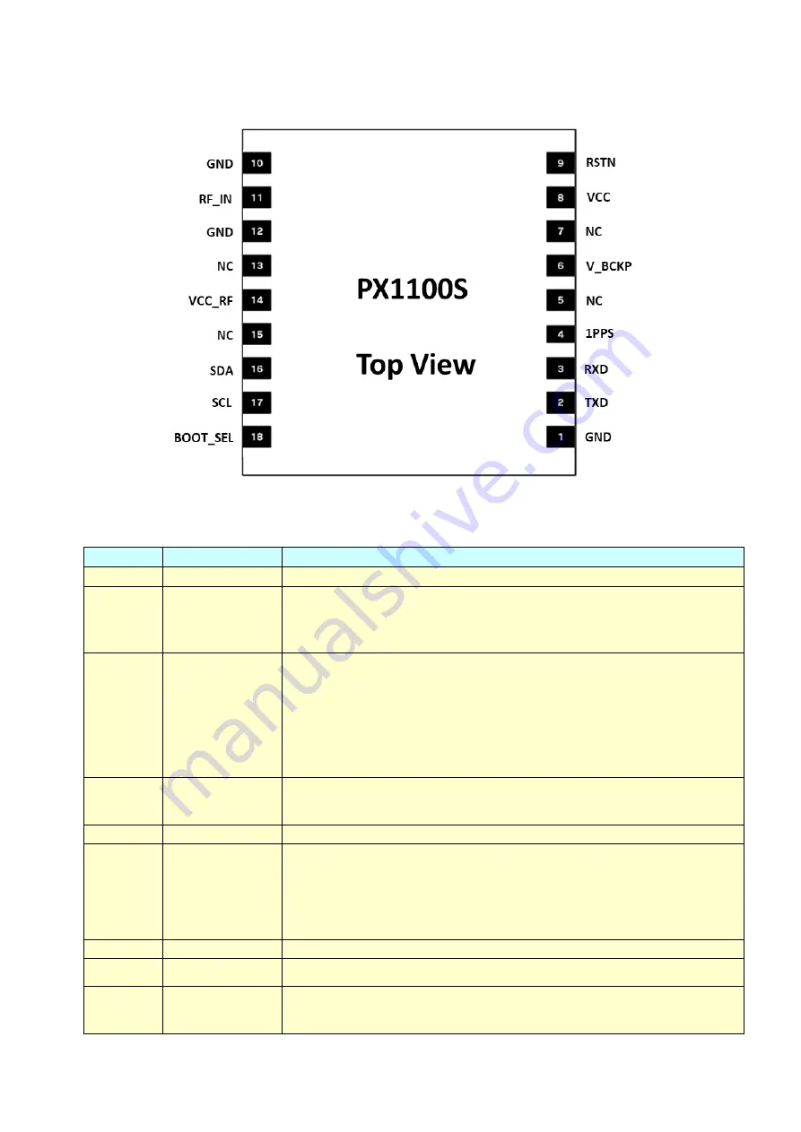
PINOUT DESCRIPTION 


Pin No. 

Name 

Description 

GND 

Ground 

TXD 

UART serial data output, 3.3V LVTTL.   
One  full-duplex  asynchronous  serial  UART  port  is  implemented.  This  UART 
output  is  normally  used  for  sending  position,  time  and  velocity  information 
from the receiver in NMEA-0183 format. When idle, this pin output HIGH. 

RXD 

UART serial data input, 3.3V LVTTL.   
One full-duplex asynchronous serial UART port is implemented. This UART input 
is  normally  for  sending  commands  or  information  to  the  receiver  in  SkyTraq 
binary  protocol.  In  the  idle  condition,  this  pin  should  be  driven  HIGH.  If  the 
driving  circuitry  is  powered  independently  of  PX1100S,  ensure  that  this  pin  is 
not driven to HIGH when primary power to PX1100S is removed, or a 10K-ohm 
series  resistor  can  be  added  to  minimize  leakage  current  from  application  to 
the powered off module. 

1PPS 

One-pulse-per-second  (1PPS)  time  mark  output,  3.3V  LVTTL.  The  rising  edge 
synchronized to UTC second when getting 3D position fix. The pulse duration is 
about 100msec at rate of 1 Hz. 

NC 

No connection, empty pin 

V_BCKP 

Backup supply voltage for internal RTC and backup SRAM, 1.3V ~ 3.6V. V_BCKP 
must  be  applied  whenever  VCC  is  applied.  This  pin  should  be  powered 
continuously  to  minimize  the  startup  time.  If  VCC  and  V_BCKP  are  both 
removed, the receiver will be in factory default mode upon power up, all user 
configuration set is lost. For applications the does not care cold starting every 
time, this pin can be connect to VCC. 

NC 

No connection, empty pin 

VCC 

Main power supply, 3.3V +/- 10% 


RSTN 

External active-low reset input to the baseband. 
Only needed when power supply rise time is very slow or software controlled 
reset is desired. 

Summary of Contents for PX1100S

Page 1: ...in a single compact SMD module The PX1100S can track all in view GPS Beidou Galileo GLONASS QZSS satellites It is fully autonomous such that once power is applied the receiver automatically searches a...

Page 2: ...e acquisition 165dBm tracking Multi path Mitigation Advanced multi path detection and suppression A GPS Server based AGPS Update Rate 1 2 4 5 8 10 20 25 Hz default 1Hz Dynamics 4G 39 2m sec2 Operation...

Page 3: ...latest single chip Phoenix GNSS receiver technology providing high performance signal acquisition and tracking The simple UART serial interface and the standard NMEA 0183 protocol make usage of PX110...

Page 4: ...1100S is removed or a 10K ohm series resistor can be added to minimize leakage current from application to the powered off module 4 1PPS One pulse per second 1PPS time mark output 3 3V LVTTL The risin...

Page 5: ...V active antenna bias on RF_IN 12 GND Ground 13 NC No connection empty pin 14 VCC_RF Output voltage RF section 15 NC No connection empty pin 16 SDA Not used Leave unconnected 17 SCL Not used Leave unc...

Page 6: ...00 degC OPERATING CONDITIONS Parameter Min Typ Max Unit Supply Voltage VCC 3 3 3 3 6 Volt Acquisition Current exclude active antenna current 75 mA Tracking Current exclude active antenna current 65 mA...

Page 7: ...2 hour for faster time to first fix powering up without needing to decoded ephemeris data from signal V_BCKP should be connected to non volatile supply above figure with V_BCKP connected to rechargea...

Page 8: ...8 SkyTraq Technology Inc Preliminary Draft www skytraq com tw MECHANICAL DIMENSIONS RECOMMANDED FOOTPRINT...

Page 9: ...w profile shown above should not be exceeded since excessive temperatures or transport times during reflow can damage the module Cooling temperature fall rate max 3 C sec ANTENNA SECTION CONSIDERATION...

Page 10: ...bility of being located remotely from the module but requires antenna power Active antenna usually costs more than passive patch antenna but the performance in low signal environments is usually bette...

Page 11: ...deg bends or a circular bend instead of a single 90 degree bend if needed Avoid vias with RF signal path whenever possible Every via adds inductive impedance Vias are acceptable for connecting the RF...

Page 12: ...GGA Time position and fix related data of the GPS receiver GNGLL Position time and fix status GNGSA Used to represent the ID s of satellites which are used for position fix When GPS satellites are use...

Page 13: ...ongitude 12100 52369 Longitude in dddmm mmmmm format Leading zeros transmitted 5 E W Indicator E Longitude hemisphere indicator E East W West 6 Quality Indicator 2 GPS quality indicator 0 position fix...

Page 14: ...de in ddmm mmmmm format Leading zeros transmitted 2 N S Indicator N Latitude hemisphere indicator N North S South 3 Longitude 12100 52369 Longitude in dddmm mmmmm format Leading zeros transmitted 4 E...

Page 15: ...e in 2D or 3D mode A Automatic allowed to automatically switch 2D 3D 2 Mode 3 Fix type 1 Fix not available 2 2D 3 3D 3 Satellite used 1 12 10 12 14 20 21 24 25 31 32 193 01 32 are for GPS 33 64 are fo...

Page 16: ...Signal ID Signal Name GPS 1 GP 0 1 2 3 4 5 6 7 8 All signals L1 C A L1 P Y L1C L2 P Y L2C M L2C L L5 I L5 Q GLONASS 2 GL 0 1 2 3 4 All signals G1 C A G1P G2 C A GLONASS M G2P GALILEO 3 GA 0 1 2 3 4 5...

Page 17: ...43 1 7D CR LF GBGSV 3 2 12 16 58 002 47 07 55 180 01 53 142 43 09 47 329 43 1 73 CR LF GBGSV 3 3 12 02 40 241 39 10 31 200 40 22 25 134 41 14 19 321 41 1 77 CR LF Field Name Example Description 1 Numb...

Page 18: ...itude 12100 52369 Longitude in dddmm mmmmm format Leading zeros transmitted 6 E W Indicator E Longitude hemisphere indicator E East W West 7 Speed over ground 000 0 Speed over ground in knots 000 0 99...

Page 19: ...de D Mode indicator A Autonomous mode D Differential mode E Estimated dead reckoning mode M Manual input mode N Data not valid P Precise S Simulator mode 5 Checksum 11 ZDA TIME AND DATE UTC day month...

Page 20: ...aq com tw ORDERING INFORMATION Model Name Description PX1100S L1 Quad GNSS Receiver Module PX1100S G L1 GPS Only Receiver Module NMEA 3 1 Output Compatible with Venus838 PX1100S GB L1 GPS Beidou Recei...

Page 21: ...ing to sale and or use including liability or warranties relating to fitness for a particular purpose consequential or incidental damages merchantability or infringement of any patent copyright or oth...

Reviews: