Skookum SK360 User Manual Download Page 5

©2008 Skookum Robotics, Ltd

9

7

Connections

The gyro normally has 3 inputs,  and 4 outputs, labeled on the top of its case. 

Note 

that  the  USB  interface  does  not  supply  power.

For  the  inputs  from  the  radio 

receiver, the connector mapping is:

Swash Setup Type

Input 1

Input 2

Input 3

120 deg eCCPM

Elevator Ch

Aileron Ch

Pitch Ch

135/140 degree eCCPM

Elevator Ch

Aileron Ch

Pitch Ch

“1-servo” mCCPM

Elevator Ch

Aileron Ch

n/a

90-deg eCCPM

Elevator Ch

Aileron Ch

Pitch Ch

Left/Right means the heli’s left and right, looking from its tail to its nose.

The SK360 needs  to  receive  separate  aileron,  elevator,  and  pitch  inputs  so 

set  the 

swash-type  in  your  radio  to  “1-servo”

for  all  swash  setups.   You  also  have  the 

option of using the “A4” port as a remote gain and bank-switching input. But do not 
connect this port to your radio until the SK360 unit is told to use it as an input with 
its setup software, or your radio receiver could be damaged (see Section 13).

For the outputs to the servos, the connector mapping is:

Swash Setup Type

Servo 1

Servo 2

Servo 3

Servo 4

120, 135/140 deg eCCPM

Centre

Right

Left

n/a

“1-servo” mCCPM

Elev

Aile

n/a

n/a

90-deg eCCPM

Fwd

Aft

Right

Left


©2008 Skookum Robotics, Ltd

10

8

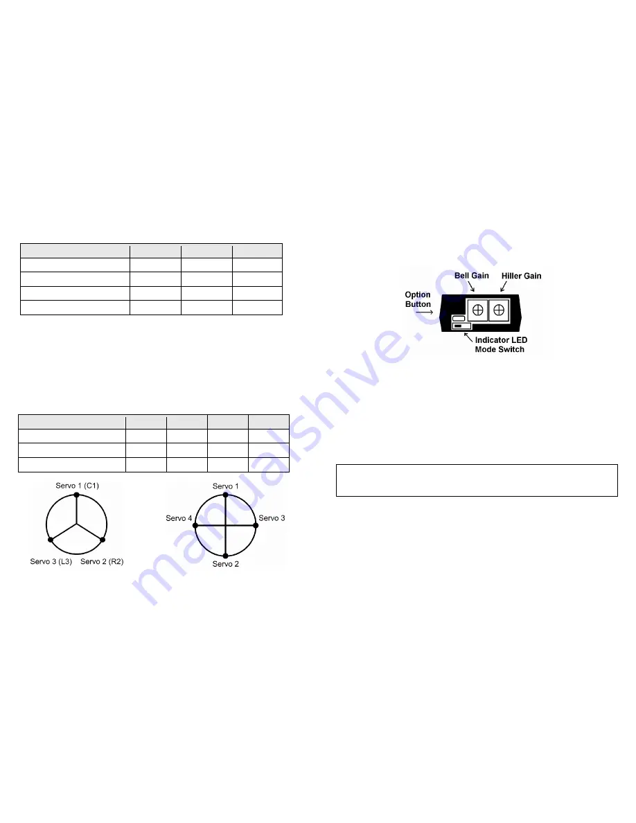
Modes, Indicators, and Power-Up

The two primary modes are Setup mode, and Flight mode, chosen by the position of 
the  small  switch  on  the  gyro’s  side.    Towards  the  gain  dials  is  Setup  mode,  and 
away from the dials is Flight Mode.

Note:

The gyro will change from Setup to Flight mode right away, but won’t change 

from Flight to Setup until you also cycle its power.

Setup mode lets you use the USB connection, and also used for mechanical setup -
control motions pass straight through, with no stabilizing action. While in this mode, 
the indicator LED will slowly flash green.

In Flight mode, the LED Indicator will show solid red while it’s still initializing, and 
turn solid green when it’s ready to fly. The gyro will not finish initializing unless it 
is completely still. It  will also  not read in new values from the gain dials until it is 
left still for a few seconds.

The option button is used for Firmware Updates (described in Appendix B).

WARNING: 

Always  check  before  flight  that  the  LED  is 

solid  green

.  If  you  take 

off  in  setup  mode  the  flight  will  be  “very  exciting”,  short,  and  possibly  also 
expensive.

The LED flashing red rapidly indicates an error. There are four possible causes:

1.

The cyclic stick wasn’t centered at initialization in flight mode

2.

The supply voltage fell below 3.6v at some point

3.

It is too hot or too cold

4.

The gyro has a systems fault

If the first three causes can be ruled out, please contact technical support.

Summary of Contents for SK360

Page 1: ...Intro 3 2 Package Contents 3 3 Safety 4 4 Mounting the Gyro 4 5 Helicopter Airframe Setup 5 6 How to Check Cyclic Pitch Phasing 7 7 Connections 9 8 Modes Indicators and Power Up 10 9 Gyro Setup Using...

Page 2: ...operty Use of this gyro places a flight control computer the gyro unit between the radio receiver and the servos that drive the swash plate If the gyro unit is mistuned or set up incorrectly loss of c...

Page 3: ...REX you can adapt the flybar mixing arms as travel reduction arms on the rotorhead to reduce the effect of swashplate slop and reduce servo load This will allow higher gains and better performance Som...

Page 4: ...with aileron centered Measure the pitch of the blade that points over the nose 4 If the mechanical setup is ideal the blade should not change pitch If it does you will need to adjust the phase angle e...

Page 5: ...and Power Up The two primary modes are Setup mode and Flight mode chosen by the position of the small switch on the gyro s side Towards the gain dials is Setup mode and away from the dials is Flight M...

Page 6: ...en Step 3 Check the Gyro s Sense Directions Now look at the Gyro Rates fields in the Live Data area Note the Rate fields only sense movement not angle Pick up the heli and slowly tilt it nose up The G...

Page 7: ...t the swash for a right roll 4 Nose up elevator stick should tilt the swash for nose up 2008 Skookum Robotics Ltd 14 12 Basic Tuning If you have set up your helicopter s mechanics properly and the cyc...

Page 8: ...een and the gyro s serial number and firmware revision should be displayed Note the servos may be slightly jittery while connected to the USB port due to noise from your computer If the software will...

Page 9: ...ld slow all the servos evenly to the maximum rate of the centre servo Servo Speed Take this from your servo manufacturer s specifications Units are in seconds per 60 degrees of motion This helps the g...

Page 10: ...slightly nose heavy 2 Check that your swash is level at min zero and max collective pitch while in Setup mode On the servo tab first adjust the swash to be level at zero pitch using the trims then use...

Page 11: ...tics Ltd 22 Symptom Problem Solution Random jitter or jumps in roll and pitch Vibration effects on the gyro Make sure it is mounted on good damping tape and doesn t contact the frame Also check for ta...

Page 12: ...revision number should show up on the top right of the USB interface display 2008 Skookum Robotics Ltd 24 Appendix C Warranty and Technical Support Warranty and Repair Skookum Robotics Ltd warrants t...

Reviews: