


NOTE
Filter 84013 and 84013A should be
mounted between delivery pump and
grease reservoir being reilled
Maximum low rate into ilter should
not exceed low rate in speciication
5
4
3
2
1*
6
7
8
9
10
11
12
13
A
B
1*
Installation
1
Shut off all grease low into grease
reservoir
2
Apply Telon-based thread sealant to all
threaded connections
3
Connect grease delivery pump outlet
hose to
1
/
2
in NPTF reill ilter inlet (
11
)
4
Connect
1
/
2
in NPTF reill ilter outlet (
12
)
to hose leading into grease reservoir
*
Indicates change
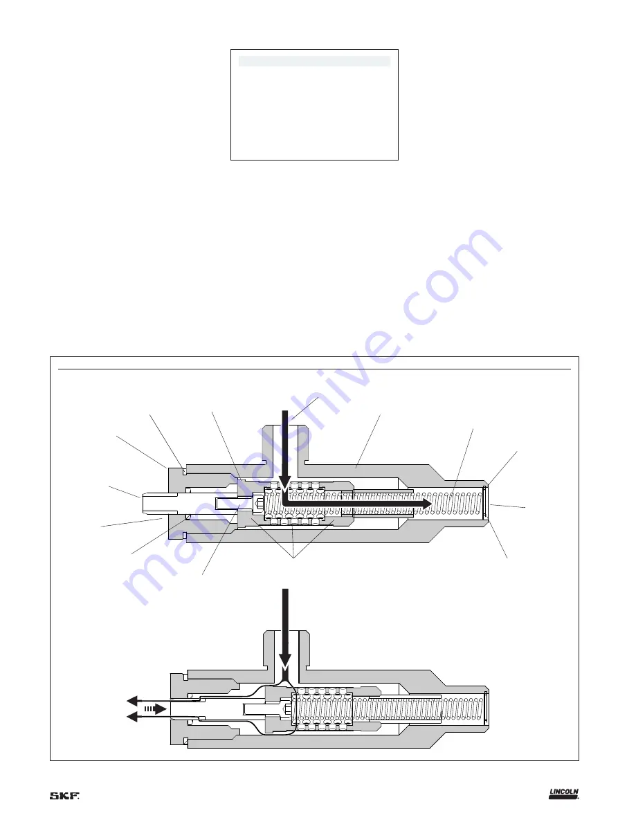
Fig. 1
Operation
Grease lows into inlet (
11
) and exits through
outlet (
12
) under normal conditions while
iltering out any impurities exceeding 250
microns in size (500 micron for 84013A)*
Under such conditions, bypass pin (
2
) is in
extended position (
Fig. 1, A
)
As contaminants are iltered out by ilter
assembly (
1
), luid pressure within ilter, or
differential pressure increases
When differential pressure from grease
ilter exceeds 200 psi
(13,8 bar)
due to
trapped contaminants, bypass pin (
2
)
retracts into ilter body (
8
) and luid bypass is
activated, releasing grease through outlet
(
13
) (
Fig. 1, B
)
.
3