


ST-800/900
Maintenance manual
14
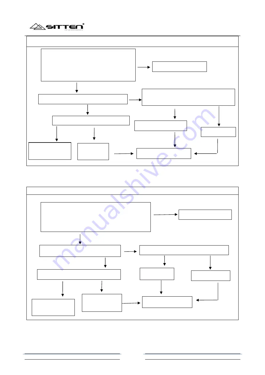
The maintenance of the main motor control circuit
11.7.2 Small motor control circuit
The maintenance of the small motor control circuit
Keep pressing “SPEED” for 3 seconds to turn
on the machine; when the display show “turn”,
then to measure the voltage of 3
rd
pin of J2 by
digital multimeter, and the voltage is 10V-20V.
The voltage of 3
rd
pin(S pole) of Q1 is 24V
N
Y
Replace the main motor
N
Test the voltage the 1
st
pin of J2 is 24V
L1 inductance
is damaged
Y
Replace the internal
switch power supply
N
Test the voltage of 41
th
pin of U6 is 1.7V-3.6V;
the voltage of 24
th
pin is around 4.8V.
Y
Q1or Q2 is damaged
N
Y
U6 is damaged
Replace the main board
Keep pressing “SPEED” for 3 seconds to turn on the
machine; when the display show “turn”, then to measure
the voltage of 1
st
pin of J3 by digital multimeter, and the
voltage is around 8.9V, the voltage of 2
nd
pin of J3 is 0V
The voltage of the first pin of U2 is 24V.
N
Y
Replace the small motor
N
Test the voltage the first pin of J2 is 24V
L1 inductance is
damaged
Y
Replace the internal
switch power supply
N
Test the voltage of the 25
th
pin of U6 is 4.6V.
Y
Q5 is damaged
N
Y
U6 is damaged
Replace the main board