background image

12 


4.9.5 Move the throttle lever to the idle position 

(a1)


Note: The operator present lever must be fully engaged to start and run trowel. If the 
lever is not engaged, engine will not run. 
 

4.9.6 Engage the operator present lever 

(e)

, if so equipped, stand to the side of the 

machine and pull the starter rope 

(j)

Do not place foot on the ring guard when starting the engine, as severe injury can occur 
if foot slips through the ring guard as the blades start to spin. 
 

Note: If the engine oil is low, the engine will not start. If engine does not start, check the 
oil level and add oil as needed. 
 

4.9.7 Open choke as engine warms 

(i2)

4.9.8 Open throttle 

(a2) 

to operate trowel. Adjust blade RPM with throttle speed to suit 

conditions. 


4.10 To Stop 


4.10.1 Reduce engine RPM to idle by moving the throttle lever to slow position 

(a1)

4.10.2 Place the Run/Stop Switch to the “

O

” (stop) position 

(b2) 

or release operator 

present lever 

(e)

4.10.3 Turn engine switch to “OFF” 

(h2)

4.10.4 Close fuel valve by moving lever to the left 

(g2)


4.11 Operation 


Choose correct blade type and attach blades to trowel arms. Do not mix float or finish 
blades with combination blades. 
 

Note: When operating on soft concrete, do not let trowel stand in one spot too long. 
Always lift trowel from slab when operation is complete. 
 
Note: “Left” and “Right” references are made from the operator's position. 
 

4.11.1 Adjust handle height to suit operator. See 

Installing and Adjusting Handles. 

4.11.2 Start engine and engage blades by increasing engine speed. Set speed with 
throttle control on handle bar to appropriate speed for job conditions. 
 
4.11.3 To move trowel forward twist handle clockwise 

(a)

4.11.4 To move backward twist handle counterclockwise 

(b)

4.11.5 To move to the left lift up slightly on the handle 

(c)

4.11.6 To move to the right press down slightly on the handle 

(d)

4.11.7 Clean trowel after each use to remove concrete splatter. 
 

Summary of Contents for SP950

Page 1: ...1 OPERATION INSTRUCTION SP950 Walk Behind Concrete Power Trowel Before using the SitePower SP950 Walk Behind Concrete Power Trowel please read this manual carefully ...

Page 2: ...Setup 8 4 3 Recommended Fuel 8 4 4 Installing Blades 9 4 5 Installing and Adjusting Handles 6 4 6 Controls 11 4 7 Run Stop Switch 11 4 8 Before Starting 11 4 9 To Start 11 4 10 To Stop 12 4 11 Operaton 12 5 Maintenance 13 5 1 Periodic Maintenance Schedule 13 5 2 Cleaning Plate 14 5 3 Drive Belt 14 5 4 Exciter Lubrication 14 5 5 Spark Plug 15 5 6 Engine Oil 16 5 7 Air Cleaner 17 5 8 Cleaning Sedime...

Page 3: ...chanical including photocopying without express written permission from SitePower Any type of reproduction or distribution not authorized by SitePower represents an infringement of valid copyrights and will be prosecuted We expressly reserve the right to make technical modifications even without due notice which aim at improving our machines or their safety standards 2 Safety Information This manu...

Page 4: ...zards associated with it 2 2 2 NEVER touch the engine or muffler while the engine is on or immediately after it has been turned off These areas get hot and may cause burns 2 2 3 NEVER use accessories or attachments that are not recommended by SitePower Damage to equipment and injury to the user may result 2 2 4 NEVER operate the machine with the beltguard missing Exposed drive belt and pulleys cre...

Page 5: ...ng Safely while using Internal Combustion Engines 2 3 1 DO NOT run machine indoors or in an enclosed area such as a deep trench unless there is adequate ventilation exhaust fans or hoses is provided Exhaust gas from the engine contains poisonous carbon monoxide gas Exposure to carbon monoxide can cause loss of consciousness and may lead to death 2 3 2 DO NOT smoke while operating machine 2 3 3 DO ...

Page 6: ... or other types of fuels or flammable solvents to clean parts especially in enclosed areas Fumes from fuels and solvents can become explosive 2 4 5 ALWAYS keep area around muffler free of debris such as leaves paper cartons etc A hot muffler could ignite them starting a fire 2 4 6 ALWAYS replace worn or damaged components with spare parts designed and recommended by SitePower 2 4 7 ALWAYS disconne...

Page 7: ...odel BS1062 Rated Power kW Hp 4 1 5 5 Engine Speed full Engine Speed idle Clutch Engagement rpm rpm rpm 3600 100 1600 100 2100 Spark Plug type NGK BPR 6ES Electrode Gap mm in 0 7 0 8 0 028 0 031 Air Cleaner type Dual Element Engine Lubrication oil grade service class SAE 10W30 SG or SF Engine Oil Capacity ml oz 600 20 Fuel type Regular unleaded gasoline Fuel Tank Capactity l qts 3 7 3 9 Valve Clea...

Page 8: ...ing grip Assembly procedures are identical for both styles 4 3 Recommended Fuel The engine requires regular grade unleaded gasoline Use only fresh clean gasoline Gasoline containing water or dirt will damage fuel system Consult engine owner s manual for complete fuel specifications 4 4 Installing Blades There are four types of blades available for the trowels Float pans are large pizza pan style b...

Page 9: ...ipe handle assembly 4 5 1 Pull the pitch control cable d from bottom end of the tube and remove the nuts from the cable 4 5 2 Thread the cable through the handle base a and over the pulley c as shown 4 5 3 Attach the pipe handle to the handle base with two M8x16 screws b Secure the screws using Loctite 243 or an equivalent medium strength thread locking compound Torque the screws to 22 Nm 16 ft lb...

Page 10: ...hen disengaging the lever the trowel should stop promptly See To Start 4 5 4 Position the handle by loosening the knob m and adjusting the handle up or down to suit the operator Tighten the knob to secure the handle in position wc_gr001100 7 5 cm 3 in 10 cm 4 in a ...

Page 11: ...matically close under certain conditions and shut off the engine For example if the operator loses his her grip on the trowel the centrifugal force created by the spinning machine will pull the switch to the O position stopping the trowel 4 8 Before Starting 4 8 1 Read and understand safety and operating instructions at beginning of this manual 4 8 2 Check Oil level in engine Fuel level Condition ...

Page 12: ...p Switch to the O stop position b2 or release operator present lever e 4 10 3 Turn engine switch to OFF h2 4 10 4 Close fuel valve by moving lever to the left g2 4 11 Operation Choose correct blade type and attach blades to trowel arms Do not mix float or finish blades with combination blades Note When operating on soft concrete do not let trowel stand in one spot too long Always lift trowel from ...

Page 13: ...aintenance Schedule The chart below lists basic engine maintenance Refer to engine manufacturer s Operation Manual for additional information on engine maintenance Daily before starting After first 20 hrs Every 2 weeksor 50 hrs Every month or 100 hrs Every year or 300 hrs Check fuel level Check engine oil level Inspect fuel lines Inspect air filter Replace as needed Check and tighten external hard...

Page 14: ... spacers with new belts should provide the correct tension Belt deflection should be 6 10 mm 1 4 3 8 checked half way between the clutch pulley and the exciter pulley d Place unused spacers on outside of pulley 5 4 Exciter Lubrication Figure 4 The exciter assembly is a self contained sealed unit The bearings are lubricated using automatic transmission fluid see Technical Data for type Change fluid...

Page 15: ... engine owner s manual The muffler becomes very hot during operation and remains hot for a while after stopping the engine Do not touch the muffler while it is hot Note Refer to the Technical Data for the recommended spark plug type and the electrode gap setting 5 5 1 Remove spark plug and inspect it 5 5 2 Replace plug if the insulator is cracked or chipped 5 5 3 Clean spark plug electrodes with a...

Page 16: ...container under the machine to collect any liquid which drains off Dispose of this liquid in accordance with environmental protection legislation 5 6 3 all drain plug 5 6 4 Fill the engine crankcase through the oil filler opening b to the upper mark on the dipstick c Do not thread in the dipstick to check the level See Technical Data for oil quantity and type 5 6 5 When the crankcase is full reins...

Page 17: ...nd dusty conditions the elements should be maintained daily Replace an element when saturated with dirt that cannot be removed 5 7 1 Remove the air cleaner cover a Remove both elements and inspect them for holes or tears Replace damaged elements 5 7 2 Wash the foam element b in a solution of mild detergent and warm water Rinse it thoroughly in clean water Allow the element to dry thoroughly 5 7 3 ...

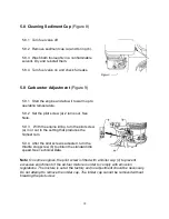
Page 18: ... removed without breaking the pilot screw 5 8 1 Turn fuel valve off 5 8 2 Remove sediment cup a and O ring b 5 8 3 Wash both thoroughly in a nonflammable solvent Dry and reinstall them 5 8 4 Turn fuel valve on and check for leaks 5 9 1 Start the engine and allow it to warm up to operating temperature 5 9 2 Set the pilot screw a 2 turns out See Note 5 9 3 With the engine idling turn the pilot screw...

Page 19: ... by its cage a and lifting slot b 5 11 4 Lift the machine as shown 5 11 5 Change engine oil and follow procedures described in engine manual for engine storage 5 11 6 Cover plate and engine and store in a clean dry area If plate is being stored for more than 30 days 5 10 1 Remove loose stones and dirt from plate 5 10 2 Clean engine cylinder cooling fins 5 10 3 Clean or replace air filter 5 10 4 Ch...

Page 20: ... cool before transporting machine or storing indoors 5 12 1 Turn fuel valve to the off position and keep the engine level to prevent fuel from spilling 5 12 2 Tie down machine on vehicle to prevent machine from sliding or tipping over Tie machine to vehicle at points shown on ...

Reviews: