background image

  3-2 

INB 

            ON 
>3-3              INC 

(三)

Device signal switch


Press, 

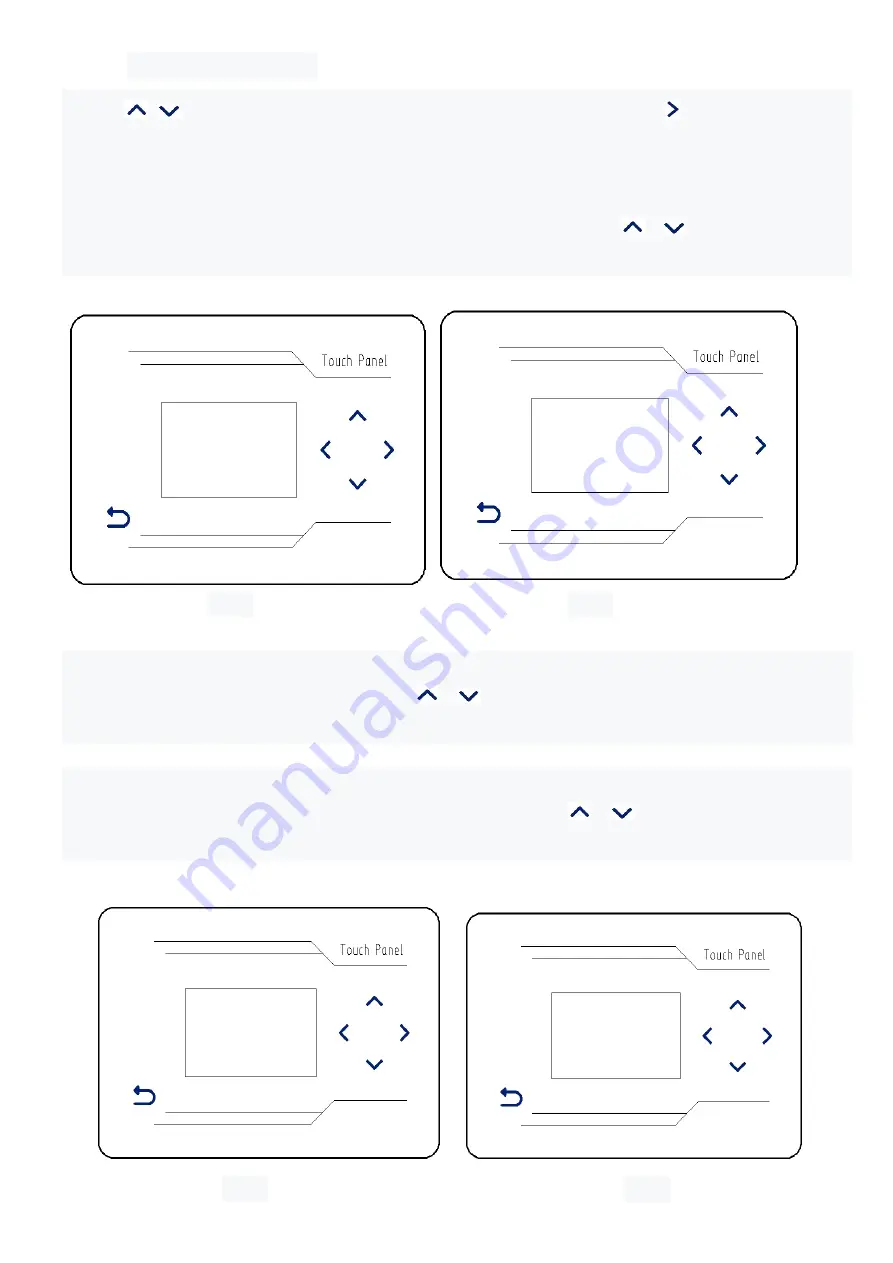
add or subtract, select "device signal switch" (FIG. 33), press   the right button, and 

enter the sub-menu interface (FIG. 34) : 
 
3-1 signal direction of knee action switch (figure 34) 

The  signal  direction  of  the  knee  action  switch  (default  ON)  is  set, 

and  the  knee  action 

switch signal can be turned off or turned ON through the add or subtract keys. 


figure

35                                                       

figure

36


3-2 step approach switch (figure 35) 

Step proximity switch (default ON) setting, 

through the key, add or subtract, you can turn 

off or open step proximity switch. 


3-3 cloth detection of electric eye signal (figure 36) 

Cloth  detection  electrical  eye  signal  (default  OFF)  setting, 

through  the  key,  add  and 

subtract, can open or close cloth detection electrical eye signal 


figure

37                                                               

figure

38


  3-3 
              INC 
              OFF 
>3-4              IND 

  3-5 
OUTA 
          OFF 
>3-6    OUTB 

  3-4 

IND 

            OFF 
>3-5            OUTA 

Summary of Contents for ASK-ACS100

Page 1: ...ASK ACS100 ELECTRONIC CONTROL PARAMETER MANUAL...

Page 2: ...P 1 ASK ACS100 1 1 3 2 3 4 5 1 2...

Page 3: ...P 2 1 1 1 2 1 2 1 3 1 2 3 4 2 3 2 3 3 1 2 3 4 1234 4 4 5 4 3 1 1 1 2...

Page 4: ...P 3 1 3 1 4 6 1 6 4 9 1 1 1 2 1 3 1 4 1 5 1 6 1 9 1 10 1 11 1 12 1 13 6 7 1 4 1 5...

Page 5: ...P 4 8 9 10 11 1 7 10 000 1 7 1 1 8 11 140V 150V 1 8 000 015V 460 470V 1 8 147V 1 9 1 5 1 6 1 6 1 7 1 7 000 1 8...

Page 6: ...P 5 1 9 1 10 1 10 1 11 1 11 1 12 12 13 1 9 12 1 9 1 10 13 1 10 14 15 1 12 001min 1 13...

Page 7: ...P 6 2 1 300 2 2 1 13 1 2 3 4 1 11 14 1 11 1 12 15 1 16 1 13 16 1 13 12 3 17 18...

Page 8: ...P 7 2 2 050 ms 2 3 2 5 2 6 17 18 2 1 18 300 19 20 2 2 19 50ms 2 3 20 15 21 22 2 4 21 1000ms 2 5 22 2 3 015 2 4 2 4 0100 10ms 2 5...

Page 9: ...P 8 2 6 010 2 7 2 8 000 ms 2 9 2 9 300 ms 2 10 2 7 000 2 8 23 24 2 6 23 10 2 7 24 0ms 25 26 2 8 25 0ms 2 9 26 300ms...

Page 10: ...P 9 2 11 300 ms 2 12 2 12 010 2 13 2 13 050 2 14 2 10 500 ms 2 11 27 28 2 10 25 500ms 2 11 26 300ms 29 30 2 12 29 10 2 13 30 50...

Page 11: ...P 10 2 14 ON 2 15 1 2 3 4 31 32 2 14 31 ON 2 15 32 33 34 33 34 3 1 34 ON 3 1 ON 3 2 2 15 000 0000 900 800...

Page 12: ...P 11 3 5 OFF 3 6 3 3 OFF 3 4 3 4 OFF 3 5 35 36 3 2 35 ON 3 3 36 OFF 37 38 3 4 37 OFF 3 5 38 OFF 3 2 ON 3 3...

Page 13: ...P 12 3 9 OFF 3 1 3 8 OFF 3 9 3 6 OFF 3 7 3 7 OFF 3 8 39 40 3 6 39 OFF 3 7 40 OFF 41 42 3 8 41 OFF 3 9 42 OFF...

Page 14: ...P 13 1 2 3 4 English A B A B 43 44 43 44 A 44 45 English 45 46 B 46 43 44...

Page 15: ...P 14 2 1 6 SR...

Page 16: ...save data 4 Move the keys left and right Move the parameters to modify the buoy under the interface of changing engineering parameters 5 Add and subtract keys to change the parameters of various funct...

Page 17: ...ings initialize the system to default parameter Settings password 1234 Interface operation instructions device function test Pass Add button Select device test Pass Right click Enter the sub menu inte...

Page 18: ...ce function test options Pass the Right click to enter the next device function test options device function test options 1 to 6 figure 4 to figure 9 1 1 FOOT TEST 1 2 INHALE TEST 1 3 GATE TWO TEST 1...

Page 19: ...button and right button turn the handwheel on the machine the encoder count value will increase by 1 for each turn positive and negative rotation can be used indicating that the encoder works normally...

Page 20: ...When covering the photoelectric sensor of fabric detection on the mechanism and the display the function state changes from open to off indicating that the fabric detection switch is normal figure 14f...

Page 21: ...election the machine will automatically loop test the above 12 functions and make corresponding actions Press the return key and the machine stops testing and returns to the upper interface figure 3 f...

Page 22: ...ubtracting keys 2 3 backward suction delayed stitches figure 20 Set the number of delayed stitches 15 stitches by default of the rear suction air The number of stitches can be adjusted to control the...

Page 23: ...r suction interval stitches 10 stitches by default The number of air suction interval stitches can be adjusted by adding or subtracting keys 2 7 feeding start delay figure 24 Start delay of feeding de...

Page 24: ...27 figure 28 2 10 delay time of pressing foot figure 27 The delay time of pressing foot is set default is 500ms The delay time of pressing foot can be adjusted by adding or subtracting keys 2 11 dela...

Page 25: ...32 2 14 working mode of electric eye for separating material figure 31 The working mode default ON of the electronic eye of material distribution is set The electronic eye switch of material distribu...

Page 26: ...be turned off or turned ON through the add or subtract keys figure35 figure36 3 2 step approach switch figure 35 Step proximity switch default ON setting through the key add or subtract you can turn...

Page 27: ...be turned on or OFF by adding or subtracting keys figure39 figure40 3 6 signal output of risk absorption control system figure 39 Risk absorption control signal output default OFF setting can be turne...

Page 28: ...43 press the right button and enter the sub menu interface FIG 44 A language setting figure 44 Press the right button to enter the sub menu interface figure 45 Press the add subtract button to select...

Page 29: ...terminal diagram Display Sensor adjust Sensor 2 Yellow Sensor 1 Red Pear swith Blue Knee switch Pear swith 6 way Solenoid Stepping motor Encoder Pedal Servo motor SR Case socket signal indication GND...

Page 30: ...The specification and or appearances of the equipment described in this parts list are subject to change because of modification which will without previous notice GS 18V02 JAN 2022...

Reviews: